Aggiornamento 28 Febbraio 2024 / 2024 February 28th update
Inserito connessione LAN all’Acom / Added LAN connection to the Acom
Aggiornamento 4 Gennaio 2024 / 2024 January 4th update
Inserita nuova Acom 600s web console / Added new Acom 600s web console
Nel capitolo “Autocostruzioni” di questo sito sono presenti soluzioni che ho pensato per “integrare” i componenti della mia stazione HF con la finalità di rispondere alle esigenze del mio modo di operare in radio.
Under “Autocostruzioni / Homebrew” menu you’ll find some solutions I thought to “integrate” my HF shack gears with the goal to match my needs and my operation habit.
I componenti principali della stazione/ Main shack components
Antenna: ho una sola antenna multibanda HF sul tetto ed una filare con accordatore SGC sul terrazzo
Antenna: I have one only multiband HF antenna on the roof and a wire on the balcony connected to SGC autotuner
Radio: normalmente uso 2 radio alternativamente
Radio: usually I run 2 rigs alternately
Amplificatore lineare: ne posseggo uno (Acom 600s)
PA: I own one PA (Acom 600s)
Accordatore d’antenna: uno automatico (Palstar HF-Auto)
Antenna tuner: 1 automatic (Palstar HF-Auto)
Alimentatore: uno per tutta la stazione
Power supply: one for all gears
Computer: Apple iMac 24″
Per chiarire le ragioni che mi hanno spinto a pensare e realizzare certe soluzioni, diamo un’occhiata d’insieme allo scenario complessivo oggi in uso:
In order to clarify the reasons that drove me to design such solutions let’s take a look at whole scenario in use now here:
usare un solo alimentatore dotato delle opportune protezioni (sovracorrente, corto circuito e sovratensione di uscita) capace di alimentare una sola radio da 100 W in trasmissione (ne uso sempre solo una alla volta) e gli accessori di stazione
distribuzione dell’alimentazione selettiva in modo da tenere sotto tensione solo le apparecchiature che sono in uso (ricordo che nei moderni RTX a stato solido anche da spenti se alimentati la tensione raggiunge lo stadio finale per tutto il tempo in cui è presente)
ridurre al minimo le manovre manuali in caso di cambio apparato in uso (CAT, comando Key e info di banda per l’amplificatore) , antenna mentre per i tasti preferisco averne un paio disponibili sul tavolo. Non facendo fonia in HF non mi sono preoccupato del microfono, per questo comunque c’è la mia soluzione di “Switch microfonico” qui sul sito e che uso in Vhf/Uhf)
usare un solo computer per tutte le attività sul quale girano un solo gestore del CAT (al quale i CAT di tutte le radio convergono) un solo logger un solo programma per i contest. Con il 7610 uso WinKeyer (contenuto nella DXP) in quanto Skookumlogger (applicazione Mac per i contest) con Winkeyer è perfetto
Targets:
touse one only power supply equipped with proper protections (overcurrent, short circuit and most important for me OVP Over Voltage Protection) dimensioned to feed one 100 W rig (i use one only one RTX a time) and station accessories
tohaveselective power supply distribution in order to feed only currently active gears (remember that modern solid state RTX keep final stage fed even if main switch is Off until power supply is disconnected)
tolimit as much as possible manual actions needed when I change active rig (CAT, Key and band info to PA, antenna. For CW keys I prefer having more than one key on my desk. As I don’t operate voice mode I didn’t care about microphone, for that you can see my solution I use with Vhf/Uhf rigs here in this site named “Switch microfonico v2” under “Autocostruizioni / Homebrew” menu)
to use one only computer for all activities, running unique CAT manager (all rigs are over there defined/configured), unique logger and unique contest application. With the 7610 I use WinKeyer (built inside the DXP) bacause Skookumlogger is perfect with WinKeyer
Operatività/ Operation
Per passare da una radio all’altra devo compiere le seguenti operazioni:
To switch from a rig to another I’ve to follow these few steps:
commutare l’antenna agendo sul commutatore a matrice Elad. Questa è l’unica manovra manuale perchè purtroppo l’Elad non è comandabile da remoto
switch antenna on Elad matrix switch. This is the only one manual action because the Elad has no remote interface
alimentare l’altra radio comandando dalla sua pagina web il distributore powerpole
switch power supply line to the radio I’m going to use by selecting it on my poerpole distributor web interface
30/04/2023 – aggiornato flow alla versione 1_1 / Flow updated to version 1_1(fixed deploy warning)
Questo progetto è nato dalla mia esigenza di comandare il cambio banda del mio Acom 600s da apparati diversi (evitando di dover commutare cavi/configurazioni) e di disporre di una “console” sul computer dalla quale poter inviare i comandi che tipicamente uso e conoscere lo stato del lineare senza dover spostare lo sguardo verso il display dell’Acom.
This project was designed to answer a need I had: to drive the only one PA I own using more than one rig, without switching between cables and configurations. In addition I thought it was a good idea to have a “screen console” (a sort of Local Control Box) useful for PA commmand sending and for PA status info retrieving.
Un breve video per far capire di cosa stiamo parlando
Here below a short video just to give an idea of what I’m going to show you
La dashboard
E’ stata pensata con sviluppo stretto e verticale in modo da essere posizionata a lato nello schermo.
It has been designe in a vertical thin shape to make easy to place it at a screen side
Con Automator l’ho trasformata in applicazione così ho potuto bloccarne le dimensioni e farla rimanere sempre in foreground sullo schermo.
Using Mac “Automator” I converted it into an application so I could fix its size and grant it foreground attribute.
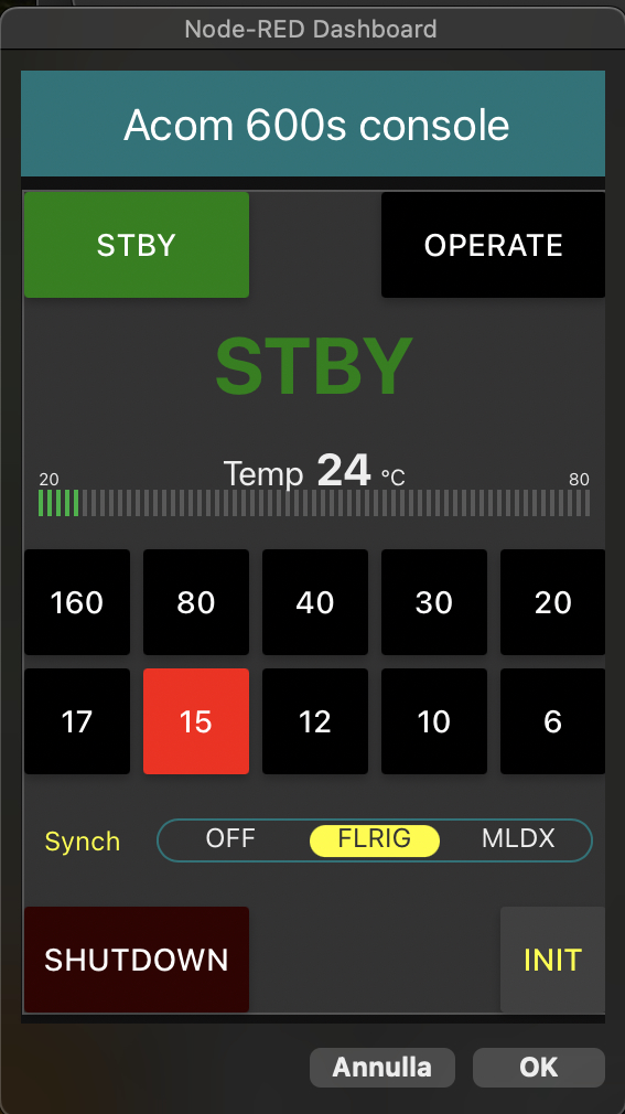
Sono presenti i comandi che tipicamente mi serve avere a portata di mano (STBY/Operate), i pulsanti di cambio banda (nel caso non sia collegata a MacLoggerDX) , il pulsante di Shutdown del lineare ed il pulsante per inizializzare l’invio dei dati di stato da parte dell’Acom. Inoltre viene mostrata la temperatura e lo stato corrente (“STBY” in verde o “Operate” in giallo o “ON AIR” in rosso) e la banda su cui è posizionato l’Acom.
On the dashboard you’ll find commands I’m used to touch during operations, so what I’d like to have under my fingers like STBY/operate, manual band change (in case not connected to MacLoggerDX), shutdown and button to initialize PA info communication. In addition to commands button the dashboard accomodates info incoming from the PA such as current temperature and operating status (“STBY” in green or “Operate” in yellow or “ON AIR” in red) and the PA band currently selected.
Al fine di avere le indicazioni mostrate nella dashboard reali ed attendibili esse NON SONO generate dal programma ma arrivano dall’Acom e sono quindi ATTUALIZZATE (infatti come potete ad esempio notare l’aggiornamento del led blu a fianco della banda corrente non è istantaneo perchè la dashboard aspetta info aggiornate dall’Acom).
Obviously the info show in the dashboard must be updated and reliable so info are NOT created by the application but they come from the PA. In this way are so sure they all are UPDATED (as you can see for example the blue led that indicates which band is selected is not immediate as soon as the rig changes it just becaus is the PA that says back to the dashboard which band is on)
Il collegamento con MacLoggerDX/ MacLoggerDX sync
Usando solo Mac il mio logger è MacLoggerDX (che di seguito indicherò con MLDX) il quale permette di configurare il collegamento CAT con più radio e quando si cambia radio basta semplicemente selezionarla dal menu ed è subito connessa via CAT (o via rete come nel caso del Flex) e disponibile. In aggiunta MLDX invia sulla rete (con cadenza temporale fissa, ma molto frequente) degli stream UDP sulla porta 9932 contenenti numerosi dati (spot selezionato dal pannello cluster, report della radio, risultati di lookup su callbook).
As I am Mac user, my logger is MacLoggerDX (since now I’ll refer it writing MLDX) than handles CAT rig with many radios, so when you decide to use another rig simply you can select it from the configured rigs dropdown list. As soon as you select another rig it is immediately CAT connected (or net connected in case of Flex) and available. Another important MLDX feature is that it sends over the network (with a very fast timing) some streams on UDP port 9932 containing several info (spot selected, radio report, callbook lookup query result).
…. non solo MLDX/ not only MLDX
Sicuramente altri logger inviano sulla rete (probabilmente in formato UDP) le informazioni relative alla radio, quindi volendo questo progetto si può adattare ad altri programmi ovviamente analizzando il contenuto degli stream UDP (o altro) prodotti dal proprio logger e correggendo di conseguenza il flow di Node-Red affinchè recuperi correttamente la banda corrente sulla radio.
I’m pretty sure that other loggers spread radio info over the network (probably using UDP too) so I think this project may be adapted to different loggers, Of course this project must be touched in order to be adapted to their messaging syntax consequentially to retrieve band info.
…. non solo con un logger / not only in junction with a logger
Sulla dashboard è previsto un’interruttore chiamato “MLDX Sync” che permette di ricevere le informazioni da MLDX. Lasciandolo in posizione Off la dashboard funziona come comando remoto per l’Acom (selezione STBY/Operate, monitor temperatura, shutdown e cambio banda mediante i pulsanti di banda e relativa segnalazione mediante led blu))
On the dashboard a switch named “MLDX Sync” allows to enable/disable info incoming from MLDX using. Leaving it in Off position the dashboard acts as a PA “remote control box” so you can manually send commands (STBY/Operate, band change, shutdown) and get status info (status, temperature, selected band)
…. non solo Acom 600s/ not only Acom 600s
A quanto ho avuto modo di leggere altri modelli Acom usano lo stesso protocollo di comunicazione via rs232 (https://static.dxengineering.com/global/images/technicalarticles/aom-600s_it.pdf). In particolare il 700s, il 1200 ed il 2000 dovrebbero funzionare senza sorprese, io ho però potuto provare solo col 600s.
As far as I red other Acom PA models use same serial communication protocol (https://static.dxengineering.com/global/images/technicalarticles/aom-600s_it.pdf). In particular 700s, 1200 and 2000 models should work as well. I could test this project only with my 600s.
Il collegamento con l’Acom 600s / Acom 600s connection
Si utilizza la porta DB9 marcata RS-232 presente sul pannello posteriore dell’Acom (NON CAT/AUX) e con un cavo la si collega o ad un’adattatore 232-Usb o alla porta seriale del computer se disponibile. La velocità di comunicazione è FISSA a 9600 baud.
One end of a serial cable wired as shown here below must be connected to Acom RS-232 DB9 connector located on its rear panel (NOT CAT/AUX connector). the other cable end will be connected to the computer via 232-USB adapter or directly to its rs232 port if available. Communication speed is FIXED at 9600 baud
Per sviluppare questo progetto ho usato Node-Red, ambiente che ritengo molto flessibile, intuitivo e capace di produrre “dashboard” di grande qualità grafica con pochisssimo sforzo e praticamente senza scrivere una sola riga di codice. Altro grande vantaggio di Node-Red è l’essere multipiattaforma (Mac, Linux e Windows) e sia per lo sviluppo che per usare la dashboard creata con Node-Red si utilizza con un qualsiasi browser (quindi fruibile anche via internet dall’esterno previa opportuna configurazione del proprio router).
To develop this project I used Node-Red because I think it’s very flexible, intuitive and able to produce very nice dashboards with limited efforts and almost without coding. Another benefit coming from Node-Red is that it’s multi-platform (Mac Linux and Windows) and for development and dashboard using only a browser is needed (so it can be used via Internet from outside too, of course after a proper router configuration).
Per implementare sul proprio computer questo progetto occorre:
installare Node-Red sul computer (Windows & Linux: https://nodered.org/docs/getting-started/local Mac: https://www.maffucci.it/2020/03/21/installare-node-js-e-node-red-su-macosx/)
è opportuno che Node-Red si avvii automaticamente al reboot del computer. A seconda del sistema operativo in uso le indicazioni per attivarlo al reboot sono diverse, qui (ma anche in molti altri siti) si trovano indicazioni al riguardo: https://nodered.org/docs/faq/starting-node-red-on-boot
una volta installato e verificato che Node-Red sia attivo al reboot (per farlo aprire col browser l’indirizzo 127.0.0.1:1880/ ) , importare il file .json di questo progetto (vedi più in basso per il download). In Node-Red gli elaborati si chiamano “Flow”. Terminata l’importazione in alto nella finestra di Node Red apparirà il flow chiamato “Acom 600s console”. La procedura di importazione è stata descritta dettagliatamente in questo mio precedente articolo: https://www.ik1bxn.it/wp/2022/11/29/wi-fi-powerpole-distributor/ al paragrafo “Installazione server”
Premere il pulsante”Deploy” (in alto a destra) e probabilmente verranno segnalati nodi mancanti (all’installazione Node-Red carica i “nodi” di default), che si possono aggiungere con facilità. In Internet o in questo articolo al paragrafo “Installazione server” si trovano informazioni più dettagliate https://www.ik1bxn.it/wp/2022/11/29/wi-fi-powerpole-distributor/
adattare i nodi della connessione seriale alla propria realtà: si deve aggiornare il nome della porta seriale alla quale è collegata la rs232 dell’Acom come dettagliatamente illustrato più avanti.
To setup this project on your computer the steps are:
install Node-red (for Windows & Linux see https://nodered.org/docs/getting-started/local for Mac see this italian page or find an english one: https://www.maffucci.it/2020/03/21/installare-node-js-e-node-red-su-macosx/)
it’s confortable to have Node-Red started after the boot. Here you’ll find instructions for supported OS https://nodered.org/docs/faq/starting-node-red-on-boot
once Node-Red has been installed and checked it’s running after reboot (simply using your browser go to this address: 127.0.0.1:1880) you’ve to import this project into your Node-Red workspace. Stated that Node-Red documents are called “flows” you’ll have to download (here below there’s download button) this project flow and import it into your Node-Red. If you need help about import you’ll find help in Internet or reading this my previous article https://www.ik1bxn.it/wp/2022/11/29/wi-fi-powerpole-distributor/ under “Server setup” paragraph. When project import phase is completed on the top Node-Red screen line the flow named “Acom 600s console” will appear
press now “Deploy” (located at top right corner) and probably you’ll be warned about some some missing nodes (at first installation Node-Red installs basic nodes set) you easily add. In internet or reading this my previous article https://www.ik1bxn.it/wp/2022/11/29/wi-fi-powerpole-distributor/ under “Server setup” paragraph you’ll find help to install missing nodes
now you have to adapt my flow to your running computer: you have to update in the flow the serial port name by selecting your computer serial port name that’s connected to your Acom
Dal momento che una porta seriale non è “facilmente” utilizzabile via rete, l’Acom DEVE essere collegato ad una porta seriale (Usb o rs232) del computer sul quale è stato installato Node-Red e caricato il flow di questo progetto.
As a serial port is not easibly reachable via network, the Acom MUST be connected to a serial port of the computer that runs Node-Red and this project flow
Per accedere a Node-Red col browser basta andare a questo indirizzo: 127.0.0.1:1880/ se siamo sul computer sul quale è installato Node-Red. Se si usa un altro computer aprire XX.XX.XX.XX:1880/ dove al posto di XX.XX.XX.XX va indicato l’indirizzo IP del computer sul quale è installato Node-Red
To access Node-Red from the computer hosting Node-Red with the browser open this address 127.0.0.1:1880/ . If you are using another netwotk computer with the browser open the address XX.XX.XX.XX:1880/ whwre XX.XX.XX.XX is the computer hosting Node-Red IP address
La dashboard sarà fruibile da qualsiasi computer della rete (o via Internet previa opportuna configurazione del proprio router) andando col browser all’indirizzo 127.0.0.1:1880/ui/ o XX.XX.XX.XX:1880/ui/ come indicato poco sopra.
To access the dashboard using browser open address 127.0.0.1:1880/ui/ or XX.XX.XX.XX:1880/ui/ as here above stated
Qui per scaricare il flow del progetto / here to download this project flow:
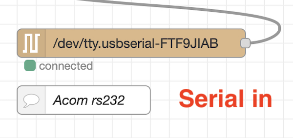
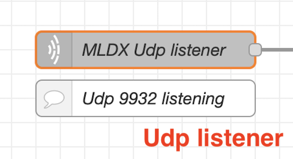
I “mattoni” principali di questo progetto sono: 1) il nodo “Serial in” che riceve i messaggi in arrivo dall’Acom – 2) il nodo “Serial out” che invia i messaggi all’Acom – 3) il nodo “Udp in” (indicato sul flow col nome “MLDX Udp listener”) che riceve gli stream UDP in arrivo da MLDX
Main “bricks”are: 1) “Serial in” node that receive Acom incoming messages – 2) “Serial out” node that sends messages to the Acom – 3) “Udp in” node (in the flow named “MLDX Udp listener”) that receives messages incoming from MLDX
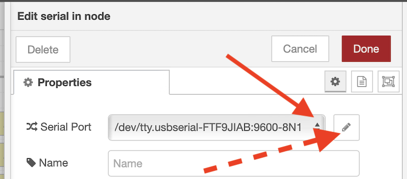
Come anticipato i nodi seriali che colloquiano con l’Acom andranno adattati alla propria realtà, ovvero andrà indicato il nome della porta seriale del proprio computer a cui è stata collegato l’Acom. Per farlo basterà fare doppio-click su un nodo seriale e si aprirà questa finestra:
As above stated the serial nodes that grant Acom communications must be adapted to your computer, I mean you must change port name indicating your computer port name that’s connected to your Acom. To do this open serial node propertied by double-clicking the node and this window will appear
dove aprendo il menu a tendina indicato dalla freccia rossa sarà possibile scegliere la porta seriale che corrisponde al collegamento con l’Acom. Volendo verificare altri parametri basterà cliccare il pulsante indicato dalla freccia rossa trattegggiata. L’altro nodo seriale dovrebbe allinearsi sulla stessa porta. Il nodo “Udp listener” invece non necessita di modifiche (a meno che non si abbia cambiato il nr della porta UDP in MLDX).
by opening dropdown list (red arrow) you can choose serial port connected to the Acom. More info are available by clicking the button indicated by dotted arrow. “Serial out” node should follow the modification. “Udp listener” don’t need to be touched (except if you modified UDP port in MLDX)
A questo punto il flow ascolta le informazioni in arrivo dall’Acom e da MLDX ed è pronto per inviare comandi all’Acom.
Now your flow is listening info incoming from the Acom and MLDX and it’s ready to send commands to the PA.
Acquisizione dei dati in arrivo dall’Acom/ Data from Acom acquisition
L’estrapolazione di quanto serve ai nostri fini dai messaggi che l’Acom invia con cadenza fissa o su evento (cambio banda ad esempio) viene fatta da questo gruppo di nodi (non ho scritto io questa parte e ringrazio George Jones K7GRJ per averla condivisa sul gruppo nodered-hamradio@groups.io)
Below shown nodes cares of retrieving data we need from the incoming info set that Acom sends trought its serial port with fixed cadence or on event (for example band change). NOTE: it’s not my development, this function was written by George Jones K7GRJ and he kindly shared it on nodered-hamradio@groups.io. Thank you so much George !!!
il cui cuore è il nodo “Function” indicato col nome “get message # then data” dove viene trattato il set di dati in arrivo e trattato quale byte di quale “array” in arrivo dall’Acom deve essere estrapolato per ottenere l’informazione desiderata (ad esempio la banda corrente). Il dato recuperato viene caricato in una variabile globale e reso disponibile per i nodi che avranno il compito di visualizzane il contenuto sulla dashboard (led acceso o barra e così via). Per dare un’idea di cosa fa il nodo funzione vediamolo un po più da vicino in maniera molto sintetica (prendendo come esempio la lettura della temperatura):
“Function” node (called “get message # then data”) treats incoming data from the PA and by pointing the correct data array and bytes inside it retrieves data we need (for example current band) for this project. Once data we need has been retrieved by the function, it loads a global variable so become available for other nodes in the flow. Let’s try to have a closer look to this function, for example the job it does to get current PA temperature:
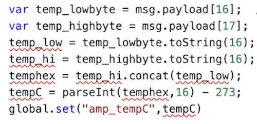
Nel ciclo “switch(fromAcom)” il primo “case 47” si occupa fra le altre attività di recuperare la temperatura dell’Acom. Leggendo la documentazione del protocollo Acom (https://static.dxengineering.com/global/images/technicalarticles/aom-600s_it.pdf) vediamo che la misura di temperatura si trova nell’array 0x2F (esadecimale che in decimale diventa 47) ai byte 16 e 17
In the cycle “switch(fromAcom)” the statement “case 47” looks for PA temperature. From the Acom protocol documentation (https://static.dxengineering.com/global/images/technicalarticles/aom-600s_it.pdf) we know that temperature measurement is reported in 0x2F array (0x2F hex means 47 decimal) at bytes 16 and 17
il dato numerico è contenuto in 2 bytes ed è espresso in °K . Per ottenere il valore in °C che porteremo sulla dashboard il nodo funzione farà i seguenti passaggi:
PA current temperature is reported using 2 bytes and expressed in °K. In order to get Celsius degrees to populate dashboard gauge the node will do following steps:
ovvero estrae dall’array 0x2F i valori dei 2 byte (16 e 17) e li carica in 2 variabili distinte (temp_lowbyte e temp_highbyte). Converte i 2 dati in stringa e con l’istruzione “concat” ottiene il valore numerico della temperatura espresso dai 2 byte insieme (temphex). Questo valore però è in formato esadecimale quindi lo trasforma in decimale (parseInt) e sottrae 273 per convertirlo da °K in °C ed infine lo carica nella variabile tempC. Per renderlo visibile dagli altri nodi del flow crea una variabile “globale” chiamata “amp_tempC” caricata col valore della variabile tempC. A questo punto la misura della temperatura (mantenuta aggiornata perchè Acom ogni 10 mS invia l’array aggiornato) è a disposizione del “gauge” a barra che la mostra sulla dashboard.
it means that the node extracts from array 0x2F byes 16 and 17 their values and loads them into 2 variables (temp_lowbyte and temp_highbyte). Next step it converts both into strings and by means “concat” instruction it obtains the whole value in hex format (temphex). This value must be converted into decimal format (parseInt) and by subtracting 273 we finally have PA current temperature in °C stored into tempC variable. To let the value available for the other flow objects (nodes, gauge) temperature measurement loads a global variable named “amp_tempC”. Now PA temperature (updated each 10 mS) can feed dashboard temperatura gauge.
Procedimento simile per ottenere lo stato (STBY/Operate) ed la banda corrente.
Similar operation to get PA Status and current band selected
Invio dei comandi all’Acom/ Commands to Acom sending
Al nodo “Serial out” vengono inviati comandi strutturati seguendo le indicazioni contenute nella documentazione del protocollo Acom sopra citato. Ogni volta che un pulsante viene premuto (o arriva un cambio banda richiesto da MLDX) un messaggio specifico contenente il comando viene inviato. Prendiamo ad esempio l’invio del comando “Operate”.
The “Serial out” node sends to the Acom commands structured as per protocol documentation above mentioned. Any time a button is pressed (or MLDX asks for a band change) a specific message is sent to the PA. Let’s analyze what happens taking as example the “Operate” command.
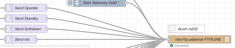
Premendo il pulsante “Operate” della dashboard viene attivato il nodo trigger chiamato “Send operate” il quale invierà il dato indicato con la freccia all’Acom attraverso il collegamento seriale
By pressing “Operate” dashboard button the “trigger” node named “Send operate” is invoked and it will send to the PA the red arrow indicated data.
vediamo cosa significa quel gruppo di numeri. Sempre facendo riferimento alla documentazione del protocollo Acom:
Let’s see what that number sequence means. Referring to protocol documentation:
per prima cosa osserviamo che Acom ha 2 tipi di “Operate” uno in Rx e l’altro in Tx. A noi interessava Operate in Rx perchè il passaggio in Tx avviene appena viene premuto il PTT della radio (sulla dashboard sono mostrati i due stati di Operate). Col messaggio in giallo “Operate” significa che l’Acom aspetta il PTT per andare in Tx (esattamente come indica il display a bordo del lineare) e con il messaggio in rosso “ON AIR” quando è in trasmissione.
first thing we may notice is that the Acom handles 2 kind of Operate status, one when in Rx and one when in Tx. For our purpose “Operate Rx” is what we need because Tx switching comes from rig PTT closing (the dashboard handles both Operate Rx and Tx). When in the dashboard you’ll see “Operate” in yellow it means the PA is waiting for PTT go into Tx (exactly as happens in Acom gear display), as soon as PA goes in TX dashboard message will turn into “ON AIR” in red.
Vediamo ora come è strutturando il comando “Operate” da inviare via rs232. I messaggi di comando al lineare sono formati da 8 bytes, il byte 0 (ovvero il primo) conterrà 0x55 (decimale 85), il byte 1 contiene 0x81 (dec 129), il byte 2 contiene la lunghezza del messaggio ovvero0x8 (dec 8), nel byte 3 troviamo il tipo di comando (ovvero una richiesta all Acom di cambiare “modo”) quindi 0x2 (dec 2), il byte 4 per il gruppo 0x2 non ha importanza quindi lo mettiamo decimale 255,il byte 5 finalmente contiene il comando che vogliamo inviare ovvero “passa in operate rx” quindi 0x0 (dec 6). Il byte 6 va messo 0 mentre il byte 7 (cioè l’ultimo) contiene il checksum dei precedenti 7 byte (calcolabile grazie ad un “checksum calculator” fruibile in Internet) e nel caso del nostro comando vale 27. Il comando “Operate rx” è pronto per essere inviato via seriale al nostro Acom:
Let’s see now how “Operate” command to be sent to PA via rs232 is built. PA message command consists of 8 bytes,in which byte nr 0 (the first one) will value 0x55 (85 in dec), byte nr 1 contains 0x81 (dec 129), in byte 2 message length is declare so 0x8 (8 dec), in byte 3 there’s the command type (in this case as we’re asking to Acom to change “mode”) it is 0x2 (2 dec), byte 4 has no relevance for 0x2 command set so we load with 255 dec, finally in byte nr 5 we put the command we are asking (turn into “Operate Rx” mode) and the value to send is 0x6 (6 dec), byte nr 6 is set to 0, byte nr 7 contains previous 7 bytes checksum (to calculate it you can use any checksum calculator you can find in Internet) and in this case its value is 27. At this point “Operate Rx” command is ready to be sent to the Acom.
Allo stesso modo vengono preparati i comandi di cambio banda e shutdown.
In the same way “band change” and “shutdown” commands are built
Cambio banda con MLDX/ Band change via MLDX
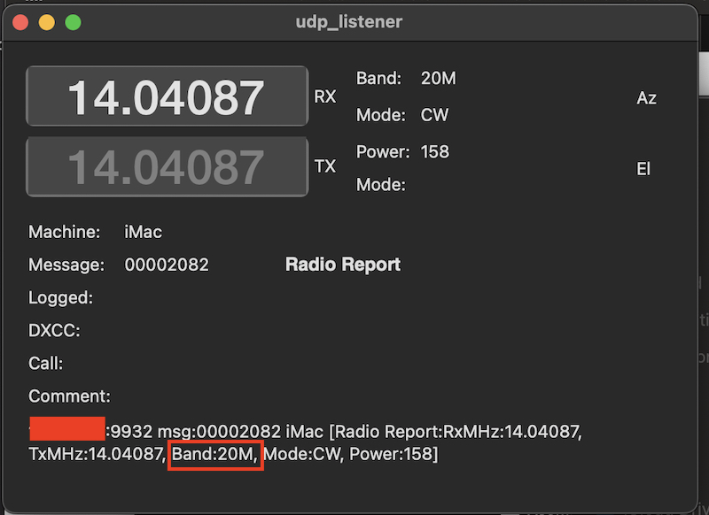
L’interfacciamento con MLDX si basa sul nodo “MLDX Udp listener” il quale riceve gli streams in arrivo da MLDX sulla porta 9932. Come già detto MLDX invia diverse informazioni in 3 tipi di stream, a noi per conoscere la banda corrente interessa solo lo stream [Radio Report….] all’interno del quale troviamo l’indicazione della banda corrente
MLDX interfacing is based on “MLDX Udp listener” node that receives all incoming streams on 9932 UDP port. As above said MLDX sends several info. In order to know rig current selected band the stream we need is the one with header [Radio Report….] inside which the band info is reported
La parte di flow dedicata alla ricezione ed al trattamento dei dati ricevuti via UDP da MLDX è la seguente:
Flow region deputed to handle UDP incoming data from MLDX is this one:
Il nodo “MLDX Udp listener” riceve tutti i dati in arrivo da MLDX e li passa al nodo “Only Radio Report”che facendo un primo filtraggio lascia proseguire solo quelli relativi al segmento [Radio Report….]. I dati poi raggiungono il nodo chiamato “MLDX Udp parser” il quale estrae ed inoltra solo l’indicazione di banda nel formato “XXM” (ad esempio 15M).
“MLDX Udp listener” node get all MLDX incoming messages and forward them to “Only Radio Report” node that does filtering and only messages containing [Radio Report….] will get out and will reach “MLDX Udp parser” (even an improper name indeed) node that will extract only band value in format “XXM” (i.e. 15M)
Sulla dashboard è presente un’interruttore che permette di attivare/disattivare il cambio banda comandato da MLDX
On the dashboard a switch allows to enable/disable band change managed by MLDX
Questo interruttore “apre” o “chiude” il nodo “gate” chiamato “Control via MLDX”. In posizione “open” il dato contenente la banda corrente arriva al nodo “switch” il quale attiva il nodo trigger della banda corrente (Send band 6m…..Send band 160m). Per comandare il cambio banda il nodo provvederà ad inviare alla seriale dell’Acom il comando di “cambio banda” costruito seguendo le indicazioni della documentazione e strutturato in maniera simile a quanto illustrato a proposito del comando Operate qui sopra. Naturalmente per ogni banda il comando conterrà al byte nr 5 un numero diverso (Acom numera le bande da 1 a 10). Ad esempio per passare in 40 m (ovvero banda nr 3 nella tabella di Acom) il comando sarà:
This switch “open” or “close” the gate node named “Control via MLDX”. In “open” position” the band info is forwarded to “switch” node that invokes current band trigger node (Send band 6m…..Send band 160m). To ask the PA to change band the band correspondant trigger node will send the appropriate command data built accordingly to protocol documentation (in similar way of “Operate Rx” request we discussed here above). Of course the command will contain at byte 5 the band number (Acom enumerates bands from 1 to 10). For example to command change to 40 m band (the nr 3 in Acom table) the command will be as follows:
Cambio banda Manuale / Manual band change
Sulla dashboard sono presenti i 10 pulsanti di cambio banda manuale
Dashboard accomodates 10 band change buttons
che come si vede sono “in parallelo” ai comandi in arrivo da MLDX. Questi pulsanti hanno senso SOLO che il sincronismo con MLDX è disattivato in quanto se MLDX dice che la radio è in 20 m e tramite pulsante si comanda il cambio a 40 m un’attimo dopo MLDX attraverso UDP dirà che la radio si trova in 20 m e l’Acom tornerà in 20 m.
As you can see they are “in parallel” with commands incoming from MLDX. These buttons have sense ONLY if MLDX sync is DISABLED because if MLDX knows the rig is in 20 m and we press 40 m button the PA move to 40 m but after a while MLDX via UDP will tell current band is 20 m and the Acom will move back to 20 m accordingly.
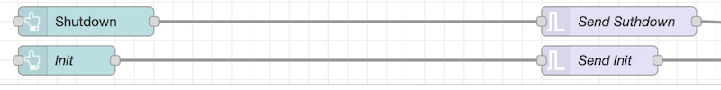
Pulsanti Shutdown e Init/ Shutdown and INIT buttons
Sulla dashboard in basso sono presenti 2 pulsanti
These more 2 buttons are located on the dashboard bottom
Shutdown permette di spegnere l’Acom senza dover agire fisicamente sul suo interruttore.
Shutdown button commands PA shutdown (without having to phisically press PA front panel button)
INIT serve ad avviare l’invio dei dati di stato (che Acom chiama “Telemetry” sulla documentazione. Qualche secondo dopo aver avviato la dashboard premendo il pulsante INIT poco dopo si illumineranno i led, la temperatura sarà aggiornata, il led di banda si accenderà a fianco della banda sulla quale si trova l’Acom ed il messaggio di stato sarà attualizzato (tipicamente STBY) . Avviato per la prima volta l’invio di dati l’Acom continuerà autonomamente ad inviarli fino allo spegnimento secondo la cadenza indicata nella documentazione.
INIT begins Acom info sending via serial port (Acom names info sending “Telemetry”). Few seconds after dashboard is started by pressing INIT button current PA band led will glow, temperature measurement and status message will be updated. Once info sending has started you don’t need to press INIT button anymore until you’ll switch Off the PA.
Come per gli altri pulsanti anche questi due attivano il relativo nodo trigger che invia alla seriale dell’Acom il comando opportuno costruito secondo le indicazioni della documentazione.
As it happens with all other buttons on the dashboard, by pressing a button correspondant node trigger is called and it sends the appropriate command built accordingly to the protocol documentation
….. that’s all folks !
spero il mio progetto vi sia piaciuto e possa essere utile per la vostra attività. Questa è la versione iniziale, in futuro penso di aggiugere nuove funzionalità Buon divertimento !!!!!
I hope you liked my project and I hope you’ll find it useful for your activity. This one is the initial release, for future I think to add additional features Have fun !!!!!
This project is based and derived from : “acom600-ldg-flex-streamdeck flow.json” available at nodered-hamradio@groups.io URL: https://groups.io/g/nodered-hamradio/files
Thanks a lot to George Jones, K7GRJ for sharing his flow
Disponendo di un solo amplificatore lineare (Acom 600s) ed operando con un paio di ricetrasmettitori avevo bisogno di poter mandare in trasmissione il lineare indipendentemente da quale radio fosse attiva e non volevo dover utilizzare ulteriori commutatori.
As I own/use a couple of rigs and I have one only PA (Acom 600s) I had the need to put PA in TX without care of which rig was in use, so avoiding a dedicated switch.
Dal momento che sono solito tenere acceso un solo ricetrasmettitore HF alla volta e commuto conseguentemente l’arrivo dell’antenna HF sul tetto (manualmente per forza dal momento che il mio commutatore a matrice Elad non prevede altro comando) ho pensato al modo di rendere “trasparente” l’inoltro del PTT (per meglio dire “Key”) al lineare.
Tipically I have one HF rig switched on at a time and I manually switch roof antenna (manually because my Elad matrix switch has no remote capability) so I thought to a solution to make PA Ptt closing (or better “keying”) as much transparent as possible.
I principali requisiti che desideravo ottenere erano: 1) mantenere il più possibile “separate” le linee di comando in uscita da ciascun Rtx – 2) fare in modo che non ci fossero ritardi aggiuntivi.
Main requirements I saw were: 1) keep keying lines ougoing from each rig as much separated as possible – 2) avoid additional delays in command
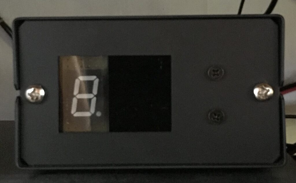
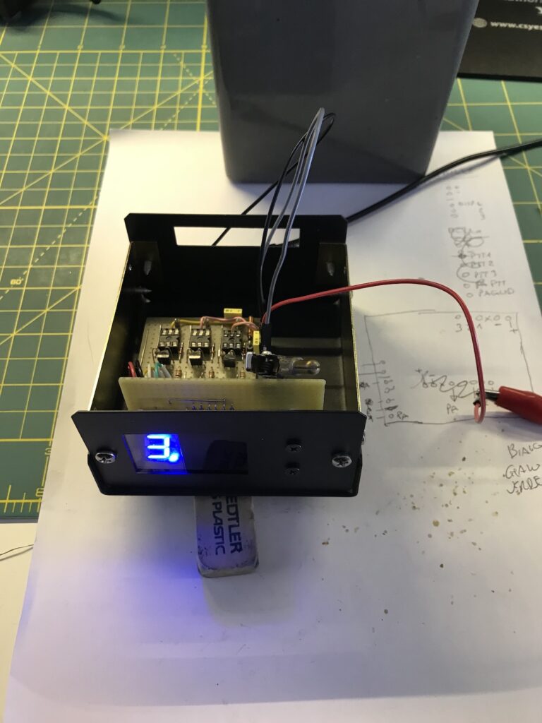
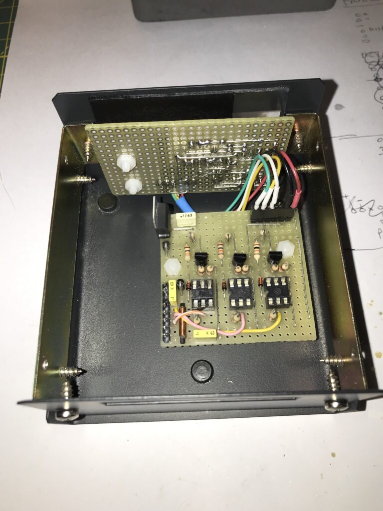
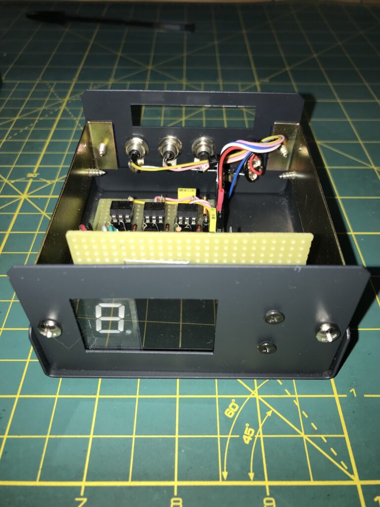
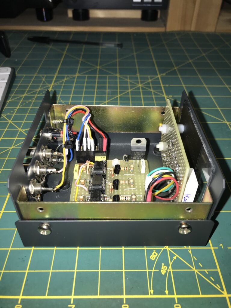
La scelta di impiegare dei fotoaccoppiatori ha soddisfatto entrambi i requisiti. Già che c’ero ho aggiunto un display a 7 segmenti che mi indica quale PTT è premuto, scelta non di sostanza nè indispensabile in quanto dei Led sarebbero andati altrettanto bene.
I decided to use optocouplers that would have matched both requirements above mentioned. I also added a 7 segment display that shows which rig number is in TX (not mandatory indeed, 3 leds would have been enough)
Appena e per tutta la durata del tempo in cui rimane premuto il PTT di una radio viene alimentato il Led del fotoaccoppiatore corrispondente attraverso una resistenza da 330 Ohm posta in serie all’alimentazione a 5 V. Immediatamente il fotoaccoppiatore manda in conduzione il transistor al suo interno mettendo così in TX l’amplificatore lineare. La corrente richiesta per attivare il comando è circa 12 mA
As soon and for the time frame the PTT of any rig is pressed the led inside the optocoupler is fed through the 330 ohm resistor connected to 5 V line. Immediately the transistor inside the optocoupler goes into conduction and switches in TX the PA. Current requirement to activate the command is about 12 mA.
Come si osserva i PTT in arrivo dalle 3 radio sono separati fra loro ed hanno in comune solo la massa (che sarebbe comunque già in comune sia per le calze dei coassiali RF sia per i negativi delle alimentazioni o dei cavi di comunicazione verso computer). Le uscite “open collector” dei 3 fotoaccoppiatori sono in parallelo per cui qualsiasi radio vada in TX il PTT del lineare viene attivato.
As you can see the PTT lines coming from the rigs are separated, only ground line is common (it would have been common anyway due to coax shields or negative power lines or computer signal cable grounding). The three optocoupler transistors are in parallel so it doesn’t matter which rig operated its PTT, the PA goes in TX.
Sulla linea di comando del lineare è presente D19 (il solito diodo utile solo se il lineare ha un relè di commutazione in TX) ed una rete C1-L1-C2 che ha lo scopo di filtare eventuali disturbi di commutazione. La corrente massima del transistor interno al fotoaccoppiatore che ho usato è pari a 50 mA con una tensione massima di 50 Vdc.
In the PA keying line I placed D19 diode (as usual diode useful if the PA has a relay to switch in TX) and the group C1-L1-C2 useful to filter possible signal perturbation. Maximum current handled by optocoupler transistor I used is 50 mA under maximum 50 Vdc.
Quando un PTT viene premuto il relativo diodo D16-D17-D18 attiva il corrispondente transistor Q1-Q2-Q3 il quale chiudendo la sua giunzione mette a massa i catodi dei gruppi di diodi D4/D5-D6/D7/D8/D9/D10-D11/D12/D13/D14/D15 i quali fanno accendere gli opportuni segmenti del display sul quale appariranno i numeri 1 o 2 o 3 coerentemente alla radio che ha premuto il PTT.
When a PTT is pressed and for the time it stays pressed the correspondant diode D16-D17-D18 drives the relevant transistor Q1-Q2-Q3 that grounds cathodes of diode groups D4/D5-D6/D7/D8/D9/D10-D11/D12/D13/D14/D15 and they will light on appropriate segments and numbers 1-2-3 will be shown.
I punto presente nel display a 7 segmenti (pin DP) è stato utilizzato come spia di ON dell’apparecchio
The displayDigit Point (DP) is used as “Power On” light.
La mia realizzazione / My built
La costruzione non presenta difficoltà nè criticità particolari. Come sempre ho usato una basetta millefori ed ho inscatolato il tutto in un contenitore metallico che presentava feritoie esistenti alle quali mi sono adeguato
Building is neither diffucult nor critical. I closed it into an iron box (coming from an estate and with existing holes)
This website uses cookies so that we can provide you with the best user experience possible. Cookie information is stored in your browser and performs functions such as recognising you when you return to our website and helping our team to understand which sections of the website you find most interesting and useful.
Cookie strettamente necessari
I cookie strettamente necessari dovrebbero essere sempre attivati per poter salvare le tue preferenze per le impostazioni dei cookie.
Se disabiliti questo cookie, non saremo in grado di salvare le tue preferenze. Ciò significa che ogni volta che visiti questo sito web dovrai abilitare o disabilitare nuovamente i cookie.