Da tempo sentivo il bisogno di avere sottomano una piccola scatola per mezzo della quale dare alla radio i comandi che uso maggiormente durante i DX, senza dover necessariamente effettuare manovre direttamente dal pannello della radio che sto usando in quel momento. I comandi ai quali mi riferisco sono: inserire/disinserire lo Split, spostare la sintonia del Vfo B, regolare la potenza, regolare la larghezza del filtro ed il volume audio
Since a time I felt the need to have “under my fingers” a small box to use to send to current rig the typical commands I use without having to touch rig front panel. Commands I’m referring to are: set Split On/Off, adjust Vfo B, adjust RF power out, adjust filter bandwidth and audio volume.
Avendo un po di esperienza nell’uso di Arduino ho subito pensato di usarlo per realizzare qualcosa che potesse gestire 4 pulsanti ed 1 encoder ai quali associare gli opportuni comandi CAT ed inviarli alla radio. Meglio ancora la mia scelta si è focalizzata su una scheda “nodeMCU” (un’Arduino ridotto che integra la parte esp8266 per il collegamento IP ad una rete Wi-Fi) che avendo a bordo la parte Wi-Fi mi consentiva di non avere ulteriori cavi di collegamento sul tavolo.
As I have a basic knowledge in Arduino I thought to use it to develop the small box to accomodate and manage 4 buttons and 1 encoder and send relevant CAT commands to current rig. Furthermore I decided to use a “nodeMCU” board (a limited in terms of I/O Arduino with integrated Wi-Fi esp8266 so capable to IP connect to a Wi-Fi network) and in this way I’d get a cordless unit, saving precious space on my desk
Il problema a questo punto era trovare il programma per il CAT più adatto per ricevere comandi via rete e passarli alla radio attiva in quel momento. Considerando che uso Mac la scelta sembrava ancora più difficile ma per fortuna ho trovato FLRIG (il gestore CAT della suite cui appartiene FLDIGI). FLRIG aveva tutte le caratteristiche a me necessarie: è “multipiattaforma (Windows, linux e Mac), è costantemente tenuto aggiornato, permette di gestire più radio e di scegliere con facilità quale gestire in ogni momento. Ma la cosa più importante per me è che FLRIG ha un’ottimo server XML-RPC ed un ampio set di comandi disponibile grazie ai quali è possibile dare comandi alla radio e chiedere informazioni indipendentemente dalla radio in uso in quel momento. In altre parole si dialoga con FLRIG sempre con lo stesso set di comandi, ci pensa poi lui a convertirli nella forma corretta per la radio attiva.
Well the hardware was defined but the problem then was to find the right CAT controller capable to accept commands incoming from the network and send them to the current rig. In addition as I’m Mac user I was afraid it wouln’t have been so simple. Luckily I found FLRIG (CAT controller from FLDIGI suite) that covered all my needs because: it’s a muliplatform application (Windows, Linux, Mac), is very very well mantained, can handle several rigs and switching from one to other is simple. But the most important feature it has that satisfies my needs is that FLRIG has a powerful integrated XML-RPC server with a very rich set of commands available. Sending commands or ask for a status to the current rig is really simple and quick, without taking care which rig is currently active and its CAT command set. Into other words you dialogue with XML-RPC server always using the same syntax, it’s up to FLRIG to properly talk with the rig using the appropriate CAT command set.
Un ringraziamento speciale a Dave W1HKJ il papà di FLDIGI ed FLRIG per la grande disponibilità mostrata nell’inserire i nuovi comandi di cui avevo bisogno ed un grande grazie a Lele IZ1UKX per avermi spinto e supportato nella realizzazione di questo progetto
A special big thanks to Dave W1HKJ (FLDIGI & FLRIG father) for the kind availability in adding the new commands I needed and the support he gave me and a big thanks to Lele IZ1UKX who spurred me and supported me with his FLRIG deep knowledge
———————————————————-
Giusto per dare un’idea ecco un breve video dove inserisco e disinserisco lo Split e regolo Vfo A e B
Just to have a glance here is a short movie in which I switch Split On/Off and adjust Vfo A and B

Il mio FLRIG Pod / My FLRIG Pod
Descrizione di funzionamento / Functional description
Vediamo ora come ho realizzato il mio Pod ovvero la versione che deriva dal mio punto di vista e che copre le mie esigenze. Naturalmente ciascuno può personalizzarlo in autonomia modificando le funzioni di pulsanti ed encoder, aggiungendo pulsanti o led o display.
Let’s have a look on how I designed my Pod . Of course this is my implementation that is based on my point of view and matches my needs. Obviously anyone may customize it by modifying buttons and encoder functions, by adding buttons or led’s or a display.

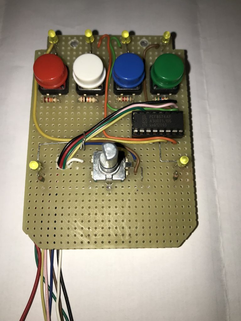
I 4 pulsanti permettono di inserire/disinserire funzionalità (nel mio caso lo Split) o inviare alla radio comandi preconfigurati (ad esempio potenza 100% o 5%) mentre l’encoder può essere associato a qualsiasi funzione si desideri. Ciascun pulsante riconosce la pressione breve o la pressione lunga (> 5 sec) premendo invece l’encoder con una pressione breve si cicla fra le 6 attribuzioni disponibili (il led segnala su quale funzione l’encoder è attivo in ciascun momento). Nella mia realizzazione ho associato pulsanti ed encoder alle funzioni che desideravo avere sottomano e con i passi di regolazione che mi sembravano più opportuni. Ovviamente è tutto modificabile agendo sullo sketch. Al momento la pressione lunga dell’encoder si limita a resettarne la posizione ma in una prossima versione intendo usarla per modificare il passo della regolazione (ad esempio +/- 100 Hz o +/- 10 Hz)
Pushbuttons are for switching on/off a function (in my case Split) or may recall some preset value (for example RF power 100% or 5%) and encoder may be assigned at any other function you like. For each button short press and long press (> 5 sec) are managed, for the ancoder only short press is implemented till now (in future I will assign it to fine/coarse step selection) and at any encoder press it cycles among 6 possible function assingnment (a Led will glow up to show which function the encoder is active to adjust)
- Per i 4 pulsanti le funzioni sono – 4 buttons functions are for:
- PF1 presssione breve SPLIT On, pressione lunga SPLIT Off – short press Split On long press Split Off
- PF2 pressione breve Potenza 100%, pressione lunga potenza 5% – short RF Power 100% long RF Power 5%
- PF3 pressione breve BW filtro 300 Hz, pressione lunga 500 Hz – short filter BW 300 Hz long filter BW 500 Hz
- PF4 pressione breve Volume 10%, pressione lunga 30% – short Volume 10% long Volume 30%
- l’encoder si può attribuire alle seguenti funzioni – Encoder function assignment
- Vfo A incrementa/decrementa a passi di +/-100 Hz – Vfo A adj step +/- 100 Hz
- Vfo B incrementa/decrementa a passi di +/-100 Hz Vfo B adj step +/- 100 Hz
- Split (al momento non regola nulla) – does nothing till now
- Potenza incrementa/decrementa a passi di +/- 5% – RF Power adj step +/- 5%
- BW filtro incrementa/decrementa a passi di +/-100 Hz – Filter BW adj step +/- 100 Hz
- Volume incrementa/decrementa a passi di +/- 5% – Volume adj step +/- 5%
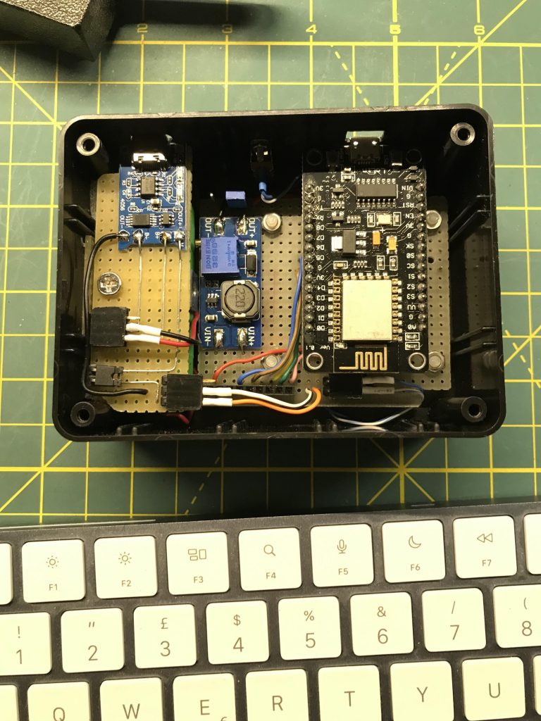
Sul fianco trovano sistemazione la presa Usb della scheda nodeMCU (usata per caricare lo sketch o per collegarla ad un monitor seriale con velocità 115200, N 8 1) l’interruttore di accensione e la presa Usb-C per ricaricare la batteria interna.
On the box side we’ll find the nodeMCU Usb port you’ll use to upload the sketch or connect a serial terminal (115200, N 8 1) the main switch and the Usb-C port for internal battery charging.

Schema elettrico / Circuit diagram
Lo schema di questo Pod è piuttosto semplice, pochi componenti e schedine già pronte per l’uso acquistate online a prezzo basso. Non vi sono criticità di montaggio l’unica cosa da tenere presente è che OVVIAMENTE venga alloggiato in un contenitore di materiale plastico dal momento che contiene anche la parte Wi-Fi. Ecco lo schema (click sul link per aprire il pdf in un nuovo pannello del browser o pulsante Download per scaricare il file)
Circuit diagram is really simple, few components are required and some little boards (battery charger and step up) ready-to-use purchased online at low price. Of course as it contains the Wi-Fi unit a plastic box is requested. Here it is (click the link to open in new browser panel or click Download to download the file pdf)
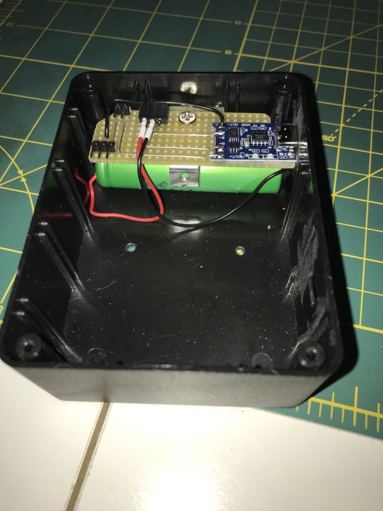
Per limitare lo spazio occupato ed essendo piuttosto contenuto l’assorbimento del circuito (circa 170 mA in standby e 220 mA in TX misurati sulla batteria) ho impiegato una sola batteria 18650. La scheda nodeMCU però quando alimentata dal pin Vin richiede una tensione di 7-10 Vdc quindi ho elevato la tensione in uscita dalla batteria al valore di 8 Vdc mediante un convertitore Step-Up Dc-Dc. La scheda nodeMCU provvede a fornire la tensione di 3.3 Vdc necessari funzionamento del resto del circuito. Per ricaricare la batteria ho utilizzato una schedina già pronta.
In order to keep overall dimensions as limited as possible, I decided to place 1 only 18650 battery. Considering that current consumption (measured at battery poles) is about 170 mA in standy and about 220 mA in TX I realized one only battery would grant me enough autonomy. The nodeMCU board requires at Vin pin 7-10 Vdc to work properly, so I foresee a Dc-Dc Step-Up-Converter that will raise voltage to 8 Vdc. The nodeMCU itself will provide 3.3 Vdc to feed the other circuit elements. To charge the battery I used a cheap ready to use little board.
L’unica cosa che va sottolineata è la gestione dei pulsanti SW3-4-5-6. Stante la limitata disponibilità di I/O della scheda nodeMCU ho dovuto usare l’unico pin analogico (A0) che la scheda ha a bordo. Come si vede dallo schema ad ogni pressione di pulsante si inserisce una resistenza nel partitore costituito da R7 + resistenza del pulsante premuto. La nodeMCU leggerà la tensione presente sul suo pin A0 e la trasformerà in un numero intero compreso fra 0 e 1023. Il programma leggendo il valore numerico capirà quale pulsante è stato premuto. Va da sè che affinchè i pulsanti vengano letti correttamente il partitore deve presentare una tensione tale da far generare un numero che corrisponda a quello che si aspetta il programma.
There’s one thing that needs to be underlined: buttons SW3-4-5-6 managment. As the nodeMCU has a limited I/O pins I had to use the unique analog pin available (pin A0) for buttons check. As you can see in the diagram any time you press a button a resistor is inserted in the resistive divider made by R7 + resistor/button/pressed. The nodeMCU will read voltage at its A0 pin and will return an intger number, the code will use this number to identify which button has been pressed. In consequence of this it’s mandatory that when you press a button the number read by nodeMCU is equal to the one the code expects
Dal momento però che le resistenze hanno tolleranze spesso del 10% potrebbe essere necessario ritoccare il programma modificando il numero che rappresenta ciascun pulsante ed inserendo quello che nel nostro montaggio risulta alla pressione dei pulsanti. Basta misurare la tensione sul pin A0 quando si preme ciascun pulsante e sapendo che quando la tensione è 3,3 V (misurare col voltmetro l’esatto valore della tensione) il numero letto dal programma è 1023 con una proporzione si ricava il numero per ciascun pulsante da correggere nel programma (dove trovate scritti i miei valori: 1013,999,970,929) ovvero
numero_da_indicare : 1023 = tensione_misurata : 3,3 (usare esatto valore)
Due to resistor tolerance (often 10%) it may be necessary to adjust in the code the number read when a button is pressed in your assembly. To do this you’ve to measure voltage at pin A0 for each button pressed, then measure the exact voltage present in our “3,3 V” line. At this point with an arithmetic proportion you can retrieve the number that corresponds to each button pressed. Now you’ve to modify the sketch by inserting your number (there you’ll find my numbers 1013,999,970,929 that come from my nodeMCU and the resistors I used)
number_to_indicate : 1023 = A0-voltage_measured : 3,3 (use the exact measured value at 3,3 line)
Questa è la parte di sketch da modificare / Sketch region involved

Per il pilotaggio dei 6 Led ho scelto di usare l’integrato PCF 8574 (8 bit I/O expander per I2C) grazie al quale impiegando solo 2 pin della nodeMCU (Scl e Sda pin D1 e D2 della nodeMCU) posso pilotare fino a 8 I/O. Nel mio utilizzo ho settato tutti gli 8 bit come output visto che dovevo pilotare 6 Led. In aggiunta essendo sul bus I2C se un domani volessi aggiungere altri Led o pulsanti mi basterebbe aggiungere un secondo PCF 8574 (indirizzandolo opportunamente sul bus I2C) così come se volessi aggiungere un display I2C. L’unica cosa a cui fare attenzione è non dimenticare di mettere a massa i pins 1-2-3 come indicato nello schema.
To drive the 6 Led’s I used an PCF 8574 ((8 bit I/O expander for I2C bus) that needs only Scl and Sda lines (nodeMCU pins D1 and D2). I configured it for all 8 bits as outputs as my need was to drive 6 Led’s. Using the I2C bus if in future more I/O will be required it will be enough to add another PCF 8574 and properly address it on the bus. Same history if an I2C display would be added. The only one thing to pay attention to is to ground pins 1-2-3 as shown in the diagram
Costruzione / My assembly
Io l’ho realizzato usando una scatola di plastica da 76x100x40 mm
II used a plastic box with dimensions 76x100x40 mm


Il programma / The code
Download sketch e librerie usate / Sketch and used libraries download
Descrizione / Description
Il programma per Arduino (ricordo che la nodeMCU si programma come un’ Arduino) è piuttosto semplice. Possiamo distinguere 5 blocchi fondamentali:
The Arduino code (remember that nodeMCU is an Arduino board compatible) is quite simple. We can distinguish 5 blocks in it
- la parte di configurazione dove vengono indicate le librerie da includere, le dichiarazioni delle variabili, i riferimenti per il funzionamento (ad esempio password Wi-Fi, indirizzo IP del computer dove gira FLRIG, bus I2C per comandare i led ecc), la configurazione di pulsanti encoder e Led / The configuration area in which we find libraries to be included, variables declaration, setup references (such as Wi-Fi password, I2C bus addressing and so on), definition for buttons-encoder-led
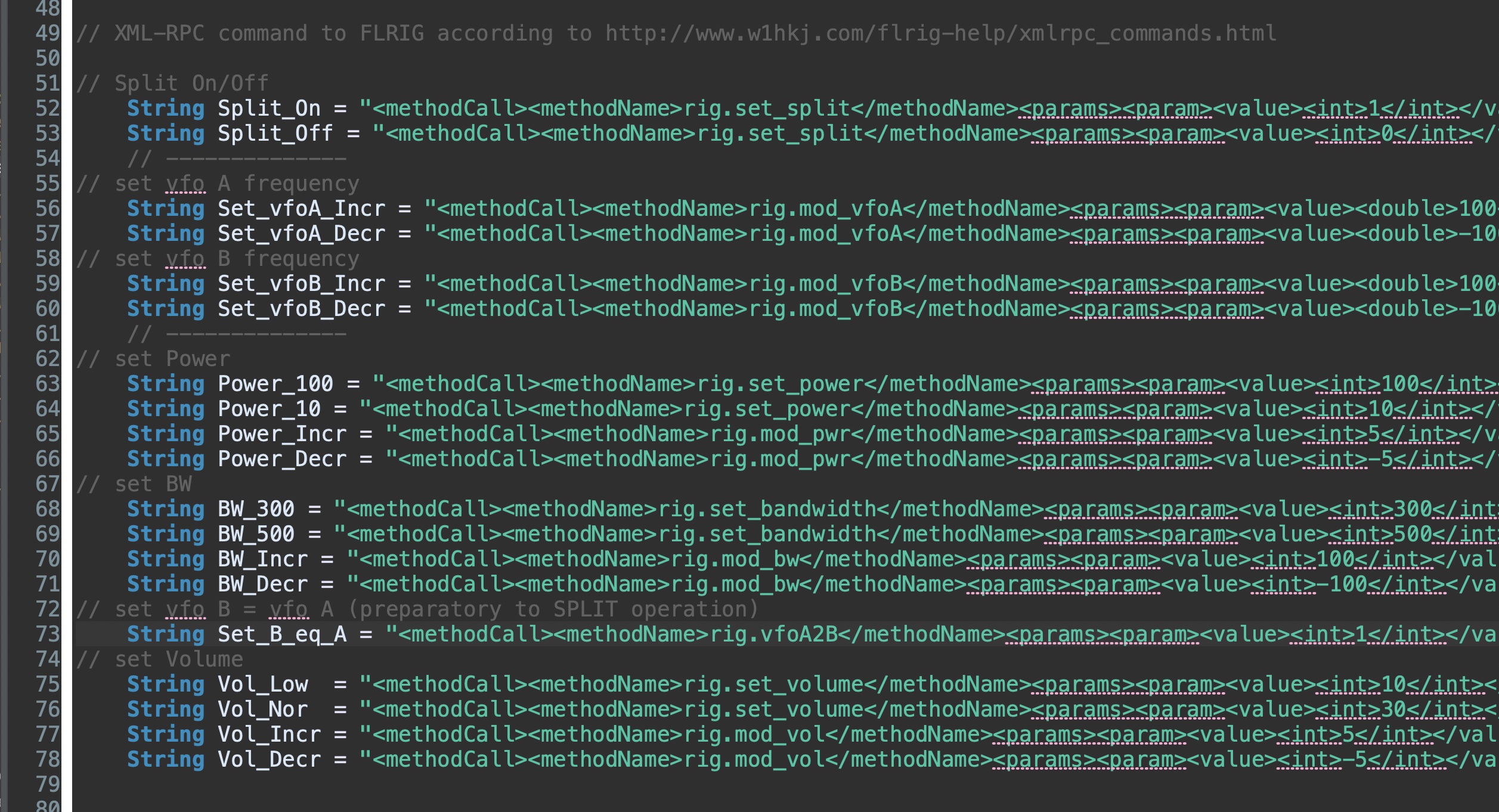
- la parte dove vengono dichiarate le variabili stringa che contengono i comandi XML-RPC che potremo inviare alla radio dal nostro Pod / Area in which XML-RPC commands we’re going to use are defined and associated to a string variable
- la funzione Setup dove vengono inizializzati i servizi che useremo (il terminale seriale ad esempio) / As always present the “Setup Funcion” that takes care of initializing resources we need (for example Serial Terminal)
- la funzione Loop che girando continuamente ascolta se vi sono eventi in arrivo da pulsanti/encoder/pulsante dell’encoder / As always the “Loop Function” that takes care continuously of listening for events by buttons or encoder or encoder button and act in consequence
- un gruppo di funzioni di servizio / A group of “service functions”
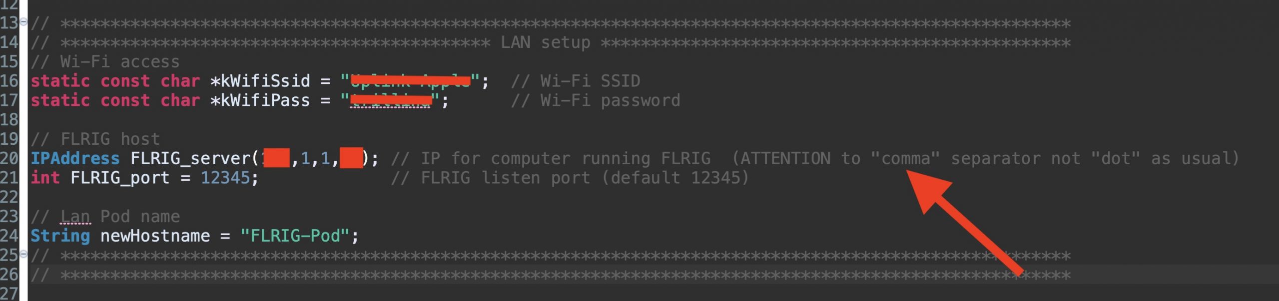
NOTA la parte di configurazione è l’unica nella quale andranno inseriti i dati della propria installazione. Per fare ciò occorre editare lo sketch (in Arduino il programma viene chiamato sketch) ed inserire i propri dati.
- nome rete Wi-Fi (SSID)
- password per accedere alla Wi-Fi
- IP Address del computer sul quale gira FLRIG (usare la VIRGOLA per separare i numeri !)
- porta sulla quale FLRIG è in ascolto (di default 12345)
- nome del nostro Pod (di default è FLRIG-Pod ma volendo si può cambiare)
REMARK the configuration area is the ONLY one part you’ll have to touch because your local data must be indicated there. To do this you’ve to edit the sketch (in Arduino world the code is called “sketch) then compile it and finally upload it to your nodeMCU. Local data to be customized are:
- Wi-Fi network SSID
- Wi-Fi password
- IP address for computer hosting FLRIG (use COMMA to separate figures instead of dots !)
- FLRIG port (12345 by default)
- FLRIG Pod Hostname by default set as FLRIG-Pod but you can place whatever name you like
Nella parte che contiene le variabili stringa dei comandi XML-RPC trovate i comandi che utilizzo nel mio Pod. A ciascuna variabile ho assegnato un nome mnemonico per renderne più comodo il loro impiego
In the area containing XML-RPC commands string you’ll find commands I’m going to use in my Pod assembly. I assigned to each command string a mnemonic variable name in order to easily recall them
I comandi disponibili sono molti di più per cui chi vuole può editare lo sketch e creare nuove stringhe XML con i comandi desiderati. Poi dovranno essere associarte ai pulsanti o all’encoder. Per visualizzare la lista dei comandi disponibili aprire FLRIG poi da Help selezionare xml-help
Available commands are many more indeed so anybody may add or substitute commands as he likes, of course to do this a basic knowledge in Arduino programming is requested. To have a look to the whole command set open FLRIG then under Help you’ll find “xml-help”.
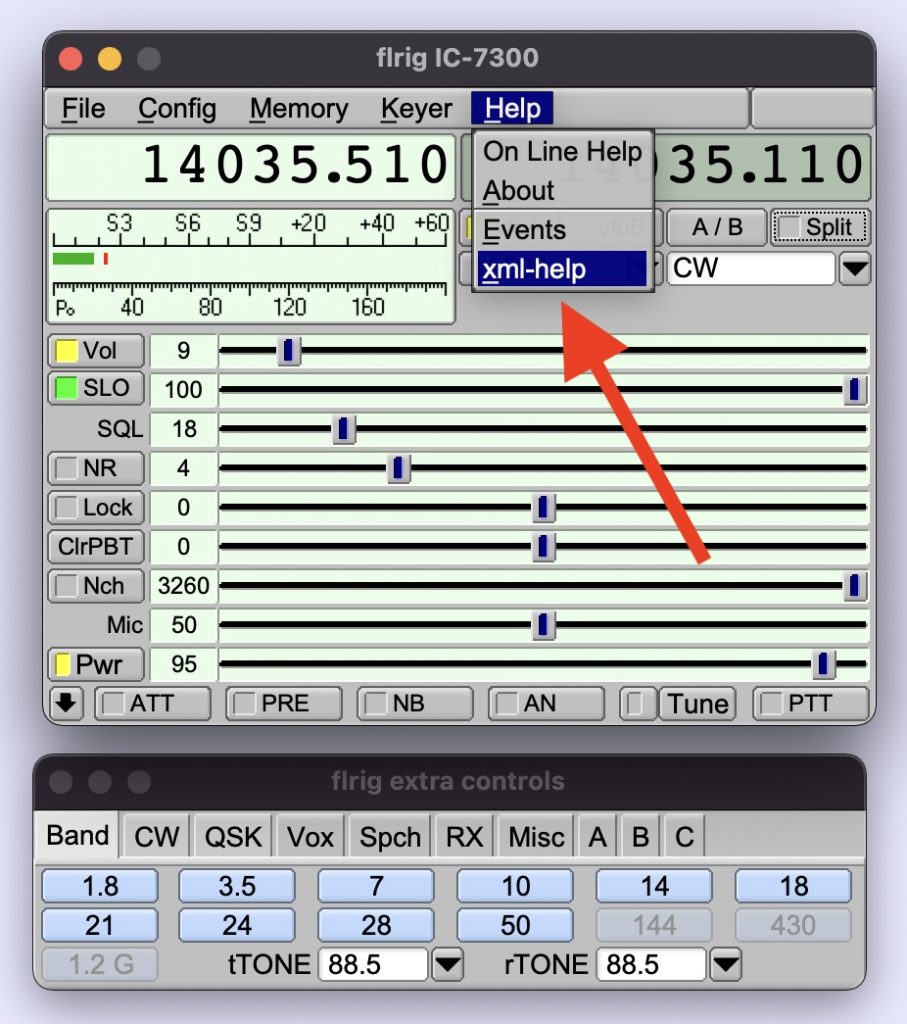
ed a questo punto si aprirà la lista dei comandi disponibili (scorrere la lista)
by clicking on “xml-help” a window will be opened and the complete command list will be shown (scroll it because is a long one)
Principio di funzionamento / How code works
Quando viene generato un’evento ad esempio il pulsante PF1 (Split On/Off nel mio caso) viene premuto il programma entra in questo punto:
When an event occours for example button PF1 has been pressed (in my case PF1 means SPLIT) this program segment will be involved

se il pulsante PF1 è stato premuto brevemente dovrà inviare il comando Split ON alla radio, come ?
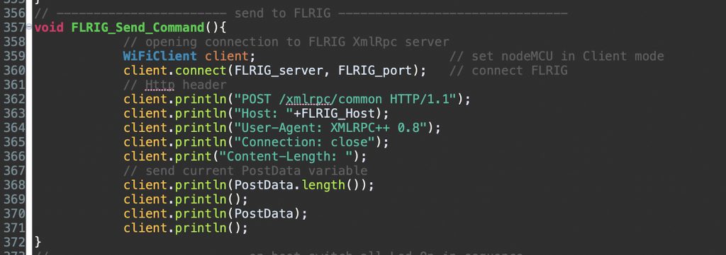
- per prima cosa dovrà mettere il Vfo B frequenza e modo uguali al Vfo A. Per farlo copierà nella variabile “di servizio” chiamata PostData il contenuto della variabile stringa xml chiamata Set_B_eq_A e chiamerà la funzione FLRIG_Send_Command la quale trasmetterà al server XML-RPC di FLRIG il comando nel formato XML (ovvero il contenuto della variabile PostData che ora contiene il comando per eguagliare il Vfo B al Vfo A) che FLRIG è in grado di capire ed eseguire
- per dare tempo ad FLRIG di attualizzare il comando ho messo un’attesa di 100 mS
- ora deve dire alla radio di mettersi in Split quindi:
- copierà nella variabile “di servizio” chiamata PostData il contenuto della variabile stringa xml chiamata Split_On e chiamerà la funzione FLRIG_Send_Command per inviarla a FLRIG
if button PF1 has been shortly pressed it means that (I’m always referring to my assembly) we’re asking to switch ON the SPLIT, how does it satisfy our request ?
- first of all it will set Vfo B frequency and mode equal to Vfo A. To do this the content of variable named Set_B_eq_A will be copied into the “service variable” named PostData. Now PostData variable contains xml string that FLRIG will use to command the rig to set Vfo B = Vfo A.To perform the action the function named FLRIG_Send_Command will be invoked and executed.
- to let FLRIG to actualize the command just sent I placed a 100mS delay
- now it’s time to tell the rig to switch SPLIT On so
- the “service variable” named PostData will be loaded with variable named Split_On contents and sent to FLRIG by invoking FLRIG_Send_Command function
se il pulsante PF1 è stato premuto a lungo dovrà inviare il comando Split OFF alla radio, per farlo
- copierà nella variabile “di servizio” chiamata PostData il contenuto della variabile stringa xml chiamata Split_Off e chiamerà la funzione FLRIG_Send_Command per inviarla a FLRIG
if button PF1 has been long pressed it means that (I’m always referring to my assembly) we’re asking to switch OFF the SPLIT and to do that:
- the “service variable” named PostData will be loaded with variable named Split_Off contents and sent to FLRIG by invoking FLRIG_Send_Command function
Questo è il principio di funzionamento e vale per i 4 pulsanti e la rotazione dell’encoder (in questo caso l’evento è legato alla sua rotazione). L’evento generato dalla pressione dell’encoder invece non richiede la trasmissione a FLRIG in quanto serve solo ad attribuire la funzionalità dell’encoder ad una delle 6 scelte possibili
The above described functional principle covers for all events coming from the 4 buttons and encoder rotation (in this case the event is generated by left/right rotation). The events generated by encoder button press are finalized to cycle encoder assignment to one of the six possible funcions so they doesn’t need to be sent to FLRIG
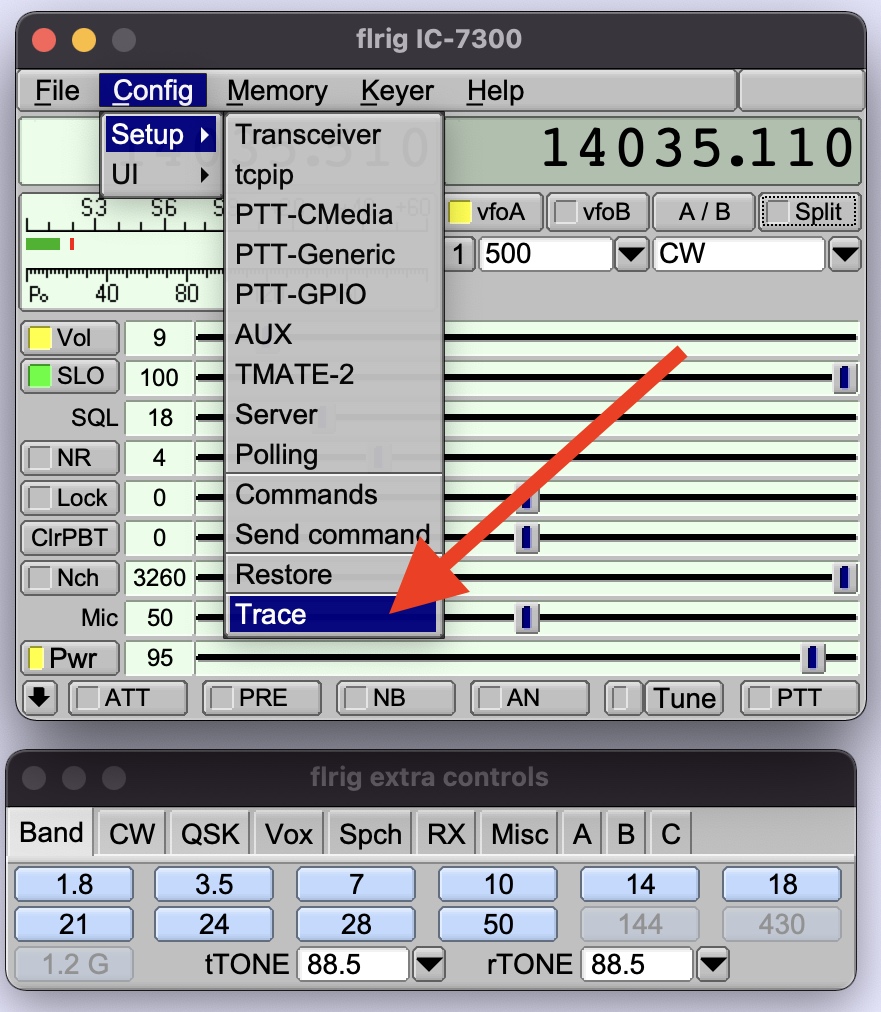
Per vedere se i comandi xml arrivano a FLRIG e se ci sono errori occorre aprire la finestra di Trace
To see monitor xml command sent to FLRIG you can open FLRIG Trace window

questo è il trace del comando Split Off
here below the trace after the command Split Off was sent

….. that’s all folks !
spero il mio progetto vi sia piaciuto e possa essere utile per la vostra attività. Questa è la versione iniziale, in futuro penso di aggiugere nuove funzionalità come ad esempio pa possibilità di inserire i dati di riferimento (Wi-Fi rete e password ad esempio) da terminale seriale senza dover modificare il programma ed una pagina web che mostri lo stato di funzionamento. Buon divertimento !!!!!
I hope you liked my project and I hope you’ll find it useful for your activity. This one is the initial release, for future I think to add additional features such as local reference data configuration via serial terminal avoiding so to touch the code and a web page that shows current status. Have fun !!!!!
TU 73 de Giorgio IK1BXN ik1bxn@ik1bxn.it
Riferimenti / Reference
- nodeMCU insight : https://lastminuteengineers.com/esp8266-nodemcu-arduino-tutorial/
- programming nodeMCU with Arduino IDE : https://create.arduino.cc/projecthub/najad/using-arduino-ide-to-program-nodemcu-33e899
- programming nodeMCU with Eclipse IDE : add Sloeber Arduino Plugin from the Marketplace
- nodeMCU firmware : https://www.espressif.com/en/products/socs/esp8266
- nodeMCU in detail : https://nodemcu.readthedocs.io/en/release/
- PCF8574 datasheet : https://www.nxp.com/docs/en/data-sheet/PCF8574_PCF8574A.pdf
- nodeMCU/esp8266 KB : https://www.iot-experiments.com/esp8266/
- W1HKJ software main page : http://www.w1hkj.com
- FLRIG alfa releases (use this link for latest release working with this Pod) : http://www.w1hkj.com/alpha/flrig/