Dal momento che uso un solo alimentatore per tutta la stazione cercavo una soluzione che mi permettesse di alimentare solo gli apparati che intendo usare (ricordo che molti apparati moderni anche da “spenti” ma alimentati mantengono in tensione lo stadio finale). Stante la mia scarsa disponibilità di spazio (vedi miei progetti precedenti “salvaspazio”) pensavo ad un distributore delle alimentazioni che non avesse comandi frontali e mi permettesse quindi di posizionarlo fuori dalla zona operativa. Ho citato i PowerPoles perchè li impiego per tutta la mia distribuzione.
Considering that I use one power supply for my shack, I was looking for a solution letting me able to switch on only rigs I’m going to operate (many recent rigs keep PA stage fed even if their main switch is Off, I don’t like this so much). In addition as I have limited room for my shack, I thought to a box I could place out of my operation area so without front panel commands. I mentioned PowerPoles because I use them for cabling since years.
Per meglio comprendere come si integra nella mia stazione / To better understand how this “brick” is integrated in my station: https://www.ik1bxn.it/wp/2023/04/24/la-mia-integrazione-di-stazione-my-shack-integration/
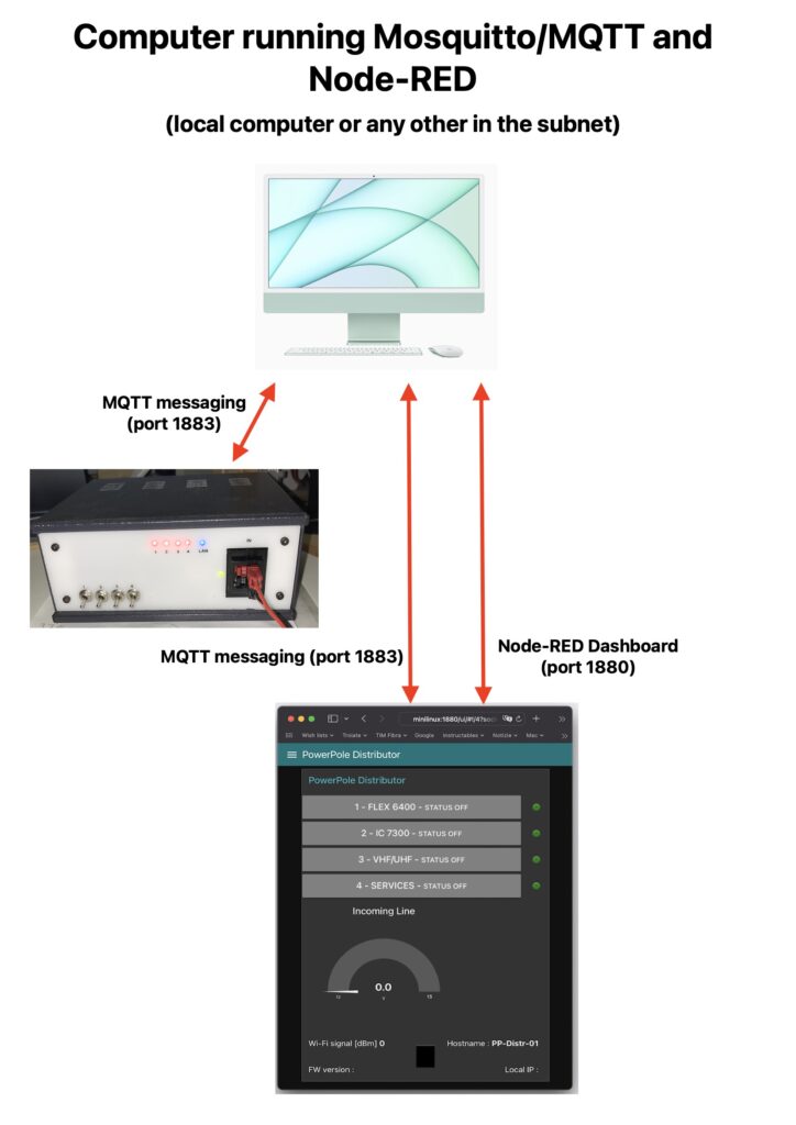
Mi sono orientato su un distributore comandato via Wi-Fi usando una pagina web mediante la quale è possibile accendere o spegnere le 4 linee di alimentazione in uscita ed avere un’indicazione attualizzata della tensione di linea. Per realizzarlo ho usato una scheda nodeMCU la quale garantisce la connessione Wi-Fi e gestisce i 4 relè che mettono in tensione le altrettante linee di alimentazione in uscita. La comunicazione fra la nodeMCU e l’interfaccia web è realizzata (nel mio caso) mediante un “server” (Ubuntu) sul quale sono in esecuzione Node-Red e Mosquitto/MQTT. La nodeMCU esegue i comandi che riceve dal server Mosquitto in formato MQTT (apri relè chiudi relè) ed invia al server le informazioni previste (stato delle linee di uscita, tensione di linea eccetera). A Node-Red spetta la generazione della “Dashboard” (che è una pagina web) mediante la quale vengono gestiti i pulsanti e pubblicato lo stato delle linee in uscita e le informazioni ricevute dalla nodeMCU. Il server Mosquitto/MQTT si occupa di veicolare le informazioni da e verso il distributore powerpole e da e verso il sistema Node-RED.
I decided to design a Wi-Fi managed box by using a webpage to switch On/Off 4 outgoing power lines and I can have a look at line voltage. I based my project on a nodeMCU board (an Arduino “relative”) that has builtin wi-fi feature. The web interface is up to Node-RED, the communication between nodeMCU and Node-RED is up to a Mosquitto server using the MQTT protocol. Both Node-RED and Mosquitto are running on a miniPC with Ubuntu. – nodeMCU does 2 jobs 1) executes relay commands coming from the Node-RED Dashboard – 2) sends info to the Node-RED Dashboard. – Node-RED takes care of 1) publishing the Dashboard command buttons – 2) collecting and publishing info coming from the nodeMCU. – Mosquitto/MQTT server grants dialogue between the above 2 bricks
Ecco un breve video di presentazione / Here is a short video that shows how it works
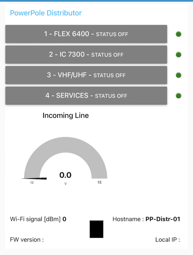
Come si può osservare dal video i comandi vengono inviati attraverso una pagina web (che può essere aperta anche da più browser contemporaneamente) la quale riporta l’indicazione dello stato di ciascuna linea mediante “led” rosso e uno verde per l’arrivo linea. Nella seconda parte del video ho evidenziato come variando la tensione di alimentazione il valore viene aggiornato (con cadenza di 0,5 secondi) e la grafica sulla pagina web cambia colore in funzione delle soglie impostate (< 12,6 V diventa gialla e > 13,7 V diventa rossa). Nella parte finale del video ho manovrato uno dei 4 interruttori che ho previsto per la chiusura manuale dei relè, utile in caso di mancanza connessione di rete.
As you can see commands to the box are sent using a web page (that may be opened by more browsers at the same time) and 4 “Led” Red and 1 Green for incoming line show the lines status. In the second part of the video I vary the incoming line voltage and its value is shown in the voltage gauge (refresh each 500 mS) and a coloured graphic region advices if the value is in the range or not (<12,6 Yellow, > 13,7 Red, Green if in the range). In the video final part I operate one of the 4 switches, useful to switch On outgoing lines in case of wi-fi connection fault
Funzionamento / Functional description
Il flusso della comunicazione fra i vari “mattoni” è quello qui sintetizzato
Here below the communication flow among the 3 “bricks” is shown
Ogni volta che viene premuto uno dei 4 pulsanti della Dasboard viene inviato al server Mosquitto/MQTT il comando relativo. Se ad esempio premiamo il pulsante “1 – Flex 6400” che era Off la Dashboard scriverà in formato MQTT sul topic “PP_Distr/command” il messaggio “CLOSE_1” attraverso il nodo “MQTT Out” denominato “Relay On/Off”
Any time one of the Dashboard 4 buttons is pressed a message containing the correspondant command is sent to Mosquitto/MQTT server. For example if you pressed button “1 – Flex 6400” that was Off the Dasbhoard will write on topic “PP_Distr/command” the message “CLOSE_1” using the “MQTT Out” node named “Relay On/Off”


A questo punto il server Mosquitto scriverà in formato MQTT sul topic “PP_Distr/command” il messaggio “CLOSE_1”. La node MCU che è in ascolto dei messaggi MQTT sul topic “PP_Distr/command” si troverà la variabile “message” caricata con la stringa “CLOSE_1” quindi scriverà sul terminale seriale che sta eseguendo CLOSE_1 e farà chiudere i contatti del relè 1. Contemporaneamente aggiornerà sulla dashboard il colore del “led” rosso/verde corrispondente usando il topic “relay_status”
At this point Mosquitto/MQTT server will spread on topic “PP_Distr/command” the message “CLOSE_1”. The nodeMCU that’s listening for MQTT messages on topic “PP_Distr/command” (as topic subscriber) will load its dummy variable named “message” with the string “CLOSE_1” and in consequence of this will printout in the serial terminal “Performing close command CLOSE_1” and will close Relay 1 contact by feeding its coil. Meantime it will update Dashboard red/green “led” accordingly by using “relay_status” topic.

In maniera analoga (ma in direzione opposta) la nodeMCU invia in formato MQTT le informazioni previste (stato dei relè, tensione di linea, intensità del segnale wi-fi, stato della connessione wi-fi, nome su rete ed IP del distributore powerpoles e versione dello sketch) creando messaggi che contengono le informazioni richieste sui topic dedicati. Va osservato che solo tensione di linea, stato ed intensità della connessione wi-fi vengono aggiornati ogni 0,5 secondi, le altre informazioni vengono inviate solo ad ogni boot.
In the same way (but in opposite direction) the nodeMCU sends to Mosquitto server in MQTT message format all info foreseen to be sent (relays status, incoming line voltage, wi-fi signal strenght, wi-fi connection status, Powerpole distributor hostname and IP and sketch version) by sending messages on dedicated topics. Let’s notice that only incoming line voltage, wi-fi status and signal strenght are sent each 500 mS, other info are sent only at boot time.

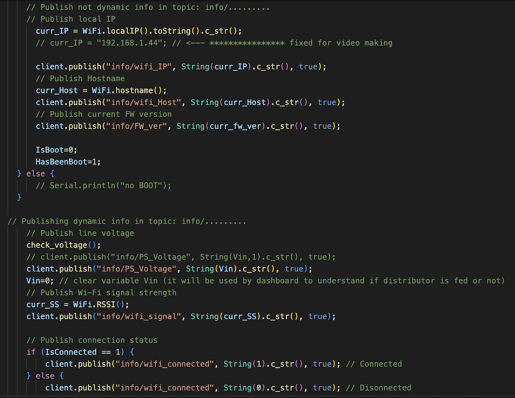
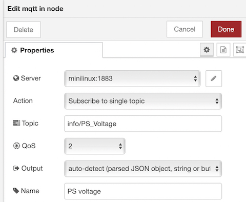
Prendiamo ad esempio l’indicazione della tensione di linea: 1) la nodeMCU misura la tensione sul pin A0 (grazie al partitore R9/R10) lo carica in forma numerica nella variabile Vin e lo invia al server Mosquitto nel topic “info/PS_Voltage”- 2) il server lo riceve lo riceve e lo passa a Node-RED dove c’è il nodo “PS voltage” in ascolto sul topic “info/PS_Voltage”
Let’s see what happens with voltage indication (for example). 1) the nodeMCU reads current incoming line voltage on its pin A0 thanks to the voltage divider R9/R10, writes it into the variable Vin and sends it to Mosquitto/MQTT server by using topic “info/PS_Voltage” – 2) the server will spread it and Node-RED node “PS voltage” that’s listening on topic “info/PS_Voltage”
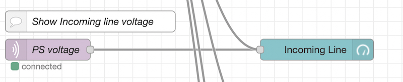
questo nodo ricevuto il messaggio (contenente il valore di tensione misurato ricevuto dalla nodeMCU) lo passerà al nodo “Incoming Line” che lo pubblicherà sulla dashboard in forma grafica e con i colori che abbiamo previsto
this node will forward the value (so incoming line voltage measured by nodeMCU) to the node named “Incoming Line” that will update the voltage gauge including coloured ranges.

Installazione server / Server setup
Per prima cosa occorre installare sul proprio computer (o su qualsiasi altro computer esistente sulla nostra rete) il “server” Mosquitto e il “server” Node-RED. Sono entrambi gratuiti e ben documentati in rete quindi la loro installazione e messa in funzione non dovrebbe creare problemi. In realtà esistono siti che offrono la gestione della messaggistica in formato MQTT (spesso usati per la “Home automation”) ma io ho preferito installarli in casa mia. Ho usato un miniPC con Ubuntu che in futuro renderò raggiungibile via Internet in modo da poter comandare questo distributore PowerPole (ed altri apparecchi) anche attraverso una connessione Internet.
First of all you need to install Mosquitto and Node-RED on your computer (or any other one in your network). Both software are free and well documented in the web so their installation/setup wouldn’t be an issue. There are also some websites offering for free MQTT for free actually (often to serve Home automation support), but I preferred install them in my network behind my router. I installed Mosquitto and Node-RED servers on a miniPC (that is cheap and very small) with Ubuntu and in future I will make it reachable from the Internet in way to operate this Powerpole distributor (and othe gears) from outside via an internet connection.
Mosquitto/MQTT download: https://mosquitto.org/download/
Node-RED download: https://nodered.org/docs/getting-started/local
Mosquitto una volta installato non ha bisogno di azioni, basta aprire sul computer che lo ospita la porta Tcp 1883 ed accertarsi è che al boot il servizio si avvii automaticamente (in rete si trovano pagine e pagine di aiuto per configurarlo e verificare il funzionamento e la fruibilità).
Node-RED una volta installato dovrebbe essere pronto per l’uso (basta aprire sul computer che lo ospita la porta Tcp 1880) e per controllarne il funzionamento basta aprire col browser l’indirizzo http://localhost:1880 (se installato su un computer diverso al posto di localhost scrivere l’IP del computer) e se node-red è attivo si aprirà questa pagina. Se non fosse attivo (su alcuni sistemi operativi occorre fare in modo che si avvii automaticamente ad ogni boot) dalla finestra del terminale digitare node-red e battere invio
When Mosquitto server installation has completed to be ready for use you have to open Tcp port 1883 on the computer hosting Mosquitto and verify that its service starts automatically at boot (many guides are available in the web to help you).
After Node-RED server installation has finished to be ready to use it you have to open Tcp port 1880 on the computer hosting Node-RED. To verify it’s running open a browser session on http://localhost:1880 (if you installed Node-RED in a different computer overwrite “localhost” with computer IP address) and if Node-RED server is up and running this webpage will be shown. In case it was not running open a console session and digit node-red followed by enter
Con Node-RED attivo la prima cosa da fare è importare il mio Flow (gli elaborati Node-RED si chiamano in questo modo). Per importarlo occorre scaricare il file (link più in basso) e salvarlo in una cartella. Per importarlo:
First step when your Node-RED up and running is to import my “Flow” (in Node-RED documents are called “Flow”). So download my Flow (link here below) save it into a folder and then

Flow download link:

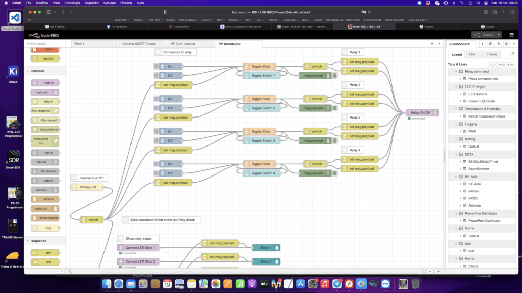
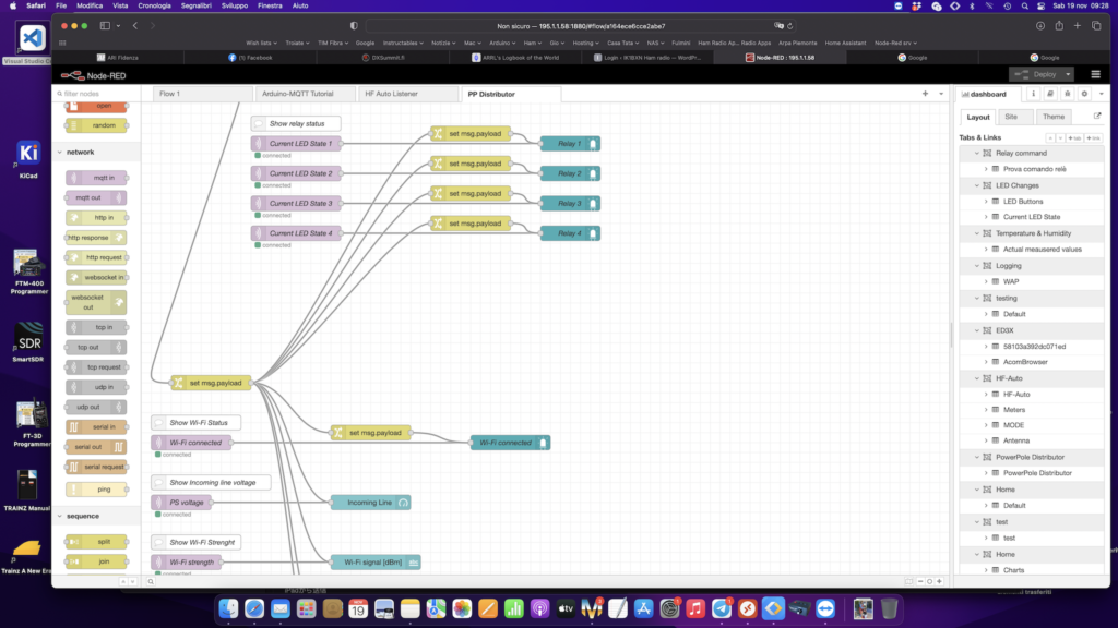
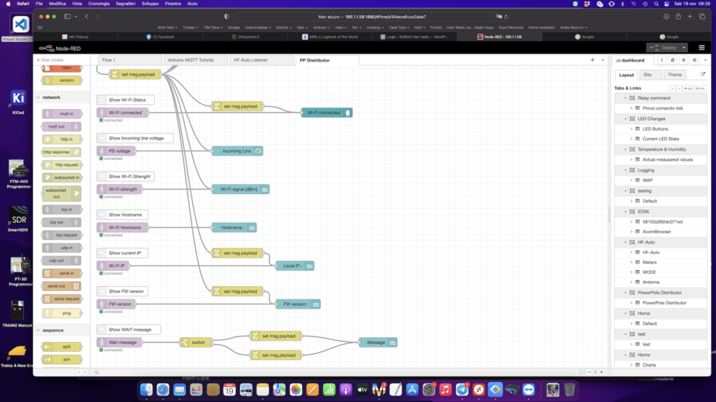
Terminata l’importazione dovreste trovare il mio Flow nel tab “PP Distributor” (la videata è stata divisa in 3 immagini)
When import has completed you should find my Flow in a tab named “PP Distributor” (top line of Node-RED webpage). Due to screen vertical size I divided it into 3 screehshots
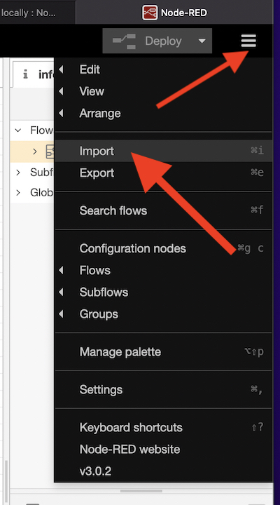
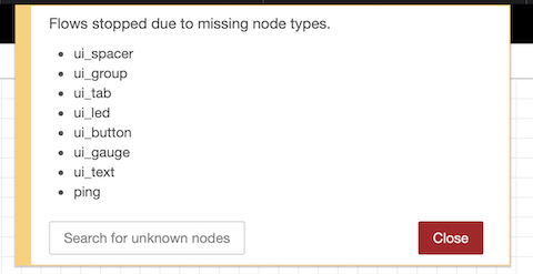
In Node-RED ogni volta che si fa una modifica per renderla operativa occorre premere “Deploy”. Eseguendo il Deploy (in alto a destra) del mio Flow molto probabilmente mancheranno i nodi che ho aggiunto per il mio Flow.
In Node-RED to actualize any modification you must “Deploy”. By pressing Deploy my Flow most likely you will be adviced that some nodes are missing (nodes I added are not installed by default)
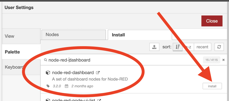
per aggiungere i nodi mancanti premere / to add missing nodes press
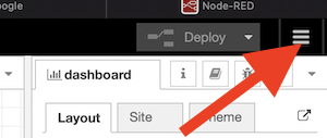
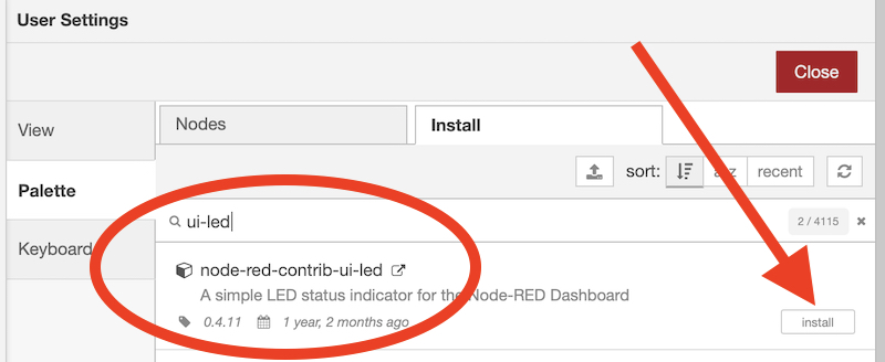
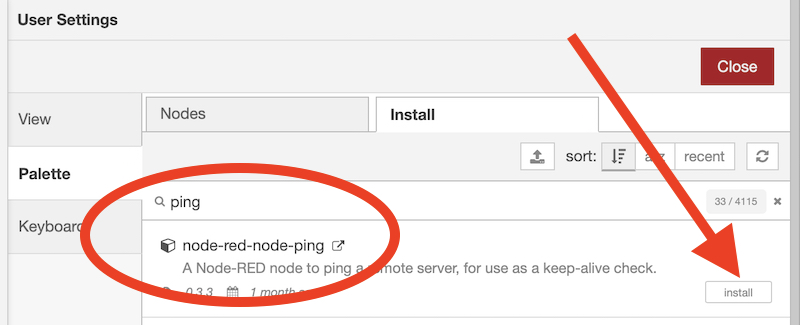
scegliere “Manage palette” e nella finestra che si apre andare su Install e digitare il nome dei nodi mancanti e premere il pulsante Install
choose “Manage palette” then go to Install tab and digit missing nodes names and press Install button
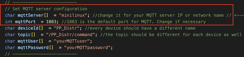
Ovviamente il mio Flow contiene i riferimenti alla mia rete, quindi dovrete modificarli inserendo i vostri. Per farlo bisogna aprire le proprietà del nodo (doppio click sul nodo) “Relay On/Off” e scrivere il nome o l’IP del computer sul quale avete installato Mosquitto. Così facendo la modifica si propagherà a tutti i nodi che usano MQTT.
Obviously the Flow you downloaded contains reference to my network objects so you have to touch it and adapt to yours. To do this you have to double click node named “Relay On/Off” and overwrite server name (for me it’s “minilinux”) with your computer running Mosquitto hostname or IP address. The modification you just did will be applied to all MQTT nodes in the Flow

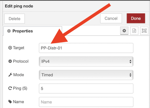
Allo stesso modo dovrà essere modificato anche il nodo “Ping” che attraverso un “ping” sente se il distributore Powerpole è attivo e presente in rete. Dovrete inserire l’Hostname del vostro distributore (se avete cambiato nello sketch il contenuto della variabile newHostname)
In the same way you must modify “Ping” node (the one that checks if Powerpole distributor is alive). So double click Ping node to open its properties and digit the hostname you assigned to your Powerpole distributor (if you touched the sketch modifying the variable newHostname)
A questo premendo nuovamente Deploy se tutto è andato a buon fine aprendo col browser l’indirizzo http://localhost:1880/ui/ (se Node-RED è installato su un’altro computer sostituire localhost con nome del computer o il suo indirizzo IP) dovrebbe aprirsi la Dashboard (ovviamente senza dati perchè ancora la nodeMCU non è attiva)
Now by pressing Deploy If everything’s was succesfull by opening with your browser the address http://localhost:1880/ui/ (if Node-RED is installed on another computer overwrite localhost with that computer name or its IP address) you should see the Dashboard (of course without data because the nodeMCU is not running)
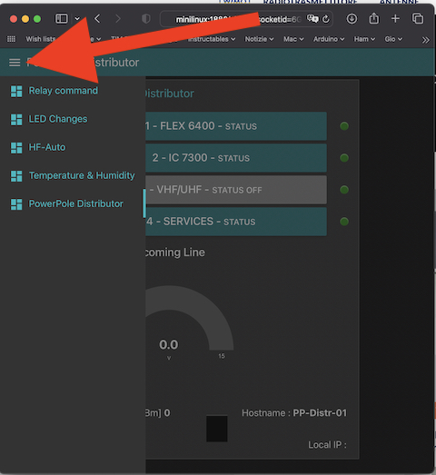
Nota: se avete più dashboards dovrete selezionare dal menu a sinistra PowerPole Distributor
TIP: if you have more than one dashboard you need to select PowerPole Distributor from top left menu
Sketch per nodeMCU / nodeMCU sketch
Vediamo ora lo sketch (ricordo che la nodeMCU si programma come fosse un Arduino) che andrà caricato nella nodeMCU.
Let’s have a look at the sketch (as I told the nodeMCU is an Arduino “relative” so to program it you’ll use Arduino IDE (or any other compatible one, I use Visual Studio for example)
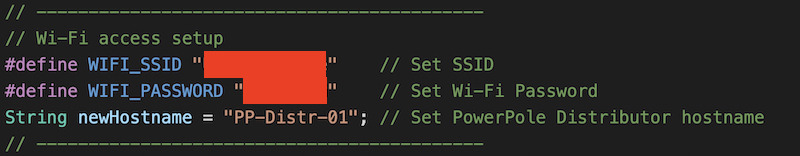
Per prima cosa andranno indicati i parametri di accesso vostra rete wi-fi ed i riferimenti della vostra rete e se preferite il nome (hostname) che verrà assegnato al vostro distributore
First of all you’ll have to touch my code in order to adapt it to your network, I mean your wi-fi SSID and its access password and (if you like) assign a different hostname to your Powerpole Distributor (remember that if you change the hostname you have to touch Node-RED Flow Ping node accordingly, as above stated)
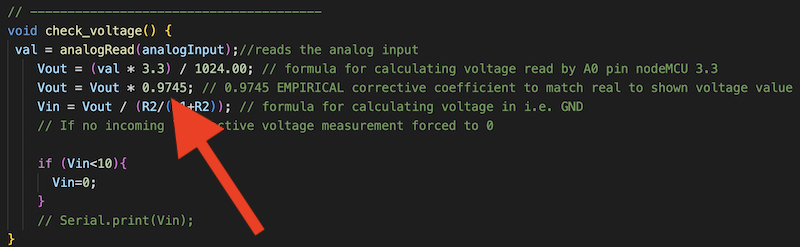
Per ottenere l’indicazione della tensione di linea il più possibile precisa (ricordo che la nodeMCU legge la tensione dal partitore R9/R10, in un range che va da 0 a 3,3 V esprimendola con un numero che va da 0 a 1023 ed usa come riferimento per la misura la sua tensione interna a 3,3 V) occorre misurare con un multimetro il reale valore delle resistenze R9 ed R10 che stiamo usando ed inserirlo nello sketch
In order to get an “accurate” voltage input readout (accurate is within quotation marks because the nodeMCU reads incoming voltage from R9/R10 divider in a range 0-3,3 V then it converts it into a number among 0 and 1023 and what’s worst this board uses internal 3,3 V as voltage reference) it’s mandatory to measure with a multimeter the exact R9 and R10 resistance value and touch the sketch by writing the measured values

In fase di collaudo finale occorrerà far coincidere l’indicazione della tensione di linea letta sulla dashboard con il reale valore misurato col multimetro. Per fare questo occorre ritoccare per tentativi il coefficiente presente nella funzione “Check_voltage” misurando col multimetro la tensione presente sul pin Vin del test point denominato TP1 e confrontandola con quella riportata sulla dashboard (che Node-RED approssima ad 1 decimale dopo la virgola)
After built has completed you’ll have to refine the code in order to get as much as possible real the incoming voltage shown by the dashboard. To do this you have to connect the mutimeter and measure incoming line voltage (TP1 test point will be useful for this action) and compare measured value with the dashboard voltage gauge indication (remember the gauge has 1 decimal approx). To get the indication real as much as possible you have to touch “EMPIRICAL corrective coefficient” by temptatives, it’s boring I know because you have to build and upload to nodeMCU any time you change it.
Per evitare che 2 pulsanti vengano premuti in sequenza troppo rapida, dopo aver premuto un pulsante occorre aspettare un tempo (default 1 secondo) prima che la pressione di un secondo pulsante sia operativa. Se non ci fosse questo potrebbe succedere che i 2 comandi vengano confusi dalla logica. Nel caso il secondo pulsante venisse premuto prima dello scadere di questo tempo sulla dashboard apparirà la scritta WAIT in giallo e si cancellaerà al termine del tempo di attesa dovuto.
In order to avoid that 2 commands are sent by the dashboard too much closely there’s a time to wait before you can send another command. In my code is set at 1000 mS. If you press a button and then another button without waiting 1 second a yellow “WAIT” message will appear in the dashboard and will disappear after 1 second

Sketch download:
Additional Library:
Schema elettrico / Circuit Diagram
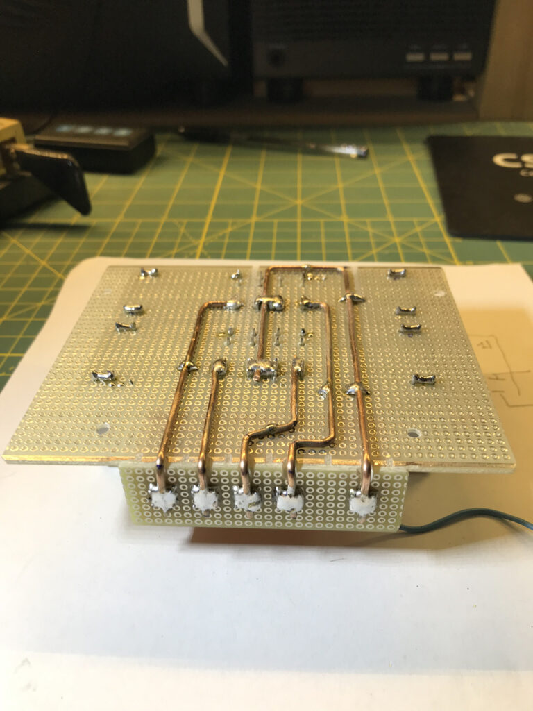
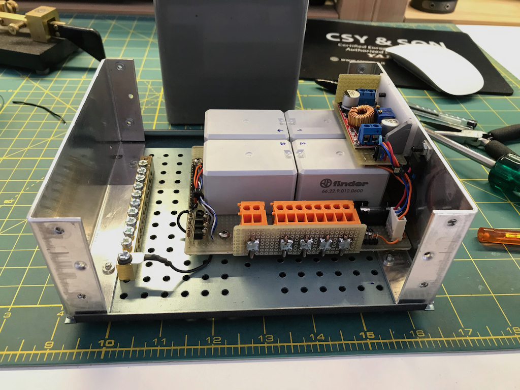
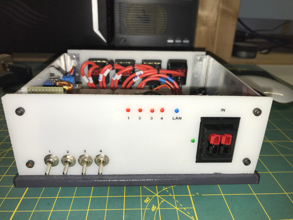
Non presenta criticità particolari. L’unica attenzione va posta nel cablaggio di potenza (indicato con linee rossa e nera di maggior spessore) per il quale occorre usare fili di sezione adeguata. Per il cablaggio di potenza sotto i relè fino alla morsettiera ho usato del filo di rame unipolare nudo da 2 mmq mentre per il cablaggio verso i connettori Powerpole di entrata e uscita ho usato del filo unipolare 14 AWG (2 mmq) molto flessibile ed isolato in silicone. Come si intuisce dallo schema ciascuna coppia di powerpole (1A-1B , 2A-2B ecc) è in parallelo sulla morsettiera di potenza (su 2 morsetti adiacenti). Ho fatto questa scelta per disporre di 2 uscite per ciascuna linea e per avere la possibilità di raddoppiare la linea di alimentazione (partendo ovviamente dallo stesso alimentatore). Per ciascuna linea in uscita è previsto un Led Rosso che si illumina quando l’uscita è attiva. La presenza tensione sulla linea di alimentazione è evidenziata da un Led Verde. Il Led Blu segnala lo stato della connessione wi-fi in quanto lampeggia durante la connessione, rimane accesso finchè è connesso ed è spento quando non è connesso (stessa indicazione viene replicata sulla dashboard dal rettangolo Blu). Premere su PowerPole-distributor-site per aprire il pdf in una nuova pagina del browser e salvarlo.
Not critical issues are foreseen. Pay particular attention to power wiring (red and black big lines in the diagram) for them you have to use wires with adequate cross section. In my built I used a naked single core copper wire 2 square millimeters in the relay board wiring (see images below) and a 14 AWG (2 sq mm) silicon flexible wire for Powerpoles wiring. As you can see each PP couple (for example 1A-1B) is in parallel at power terminal board. I did so just to have 2 connections for each line output and to have the opportunity to double incoming feeding line (originated from the same power supply of course). For each one of the 4 outgoing lines a Red Led will glow up when the line is active. There’s also a Green Led that glows when incoming line is OK. The Blue Led tells you about wi-fi connection, it blinks during connection glows solid till the connection is OK and will be Off when there’s no connection (the dashboard Blu rectangle replicates the connection OK). Here below there’s the interconnections diagram, click on PowerPole-distributor-site link to open it in pdf format in a new browser page and then save it.
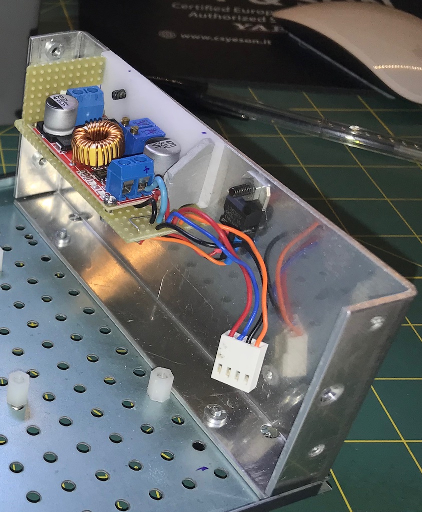
Ho anche previsto 4 interruttori SW1-SW4 con lo scopo di consentire l’accensione delle 4 linee di uscita nel caso che il distributore non fosse connesso alla rete wi-fi. L’unica messa a punto richiesta è la regolazione dello step down (indicato con U3 nello schema) per avere un’uscita a 12 V. Il test point indicato con TP1 permette agevolmente di misurare le tensioni (linea in arrivo – 12 V – 8 V). Ho preferito usare uno step down anzichè il solito 7812 perchè i relè che ho usato assorbono ciascuno 150 mA ed il 7812 chiamato a ridurre da 13,7 (tipicamente) a 12 volt con una corrente di 600 mA scaldava troppo.
4 lever switch (SW1-SW4) have been foreseen to operate the 4 outgoing lines in case of no wi-fi connection. The only one adjustment required is to regulate the step-down converter (named U3 in the diagram) in order to have 12 Vdc out (test point TP1 will be helpful). I preferred a step-down instaed of a 7812 because the relays I used have coil current around 150 mA each one and I noticed that a 7812 to reduce voltage from 13,7 to 12 Vdc with 600 mA current requires a serious heat sink.
Questo è lo schema delle interconnessioni della mia realizzazione. Premere su PowerPole-distributor-interconnections-site per aprire il pdf in una nuova pagina del browser e salvarlo.
Here’s my built interconnections schema that may be useful to better understand what we’re talking abuot at a glance. Here below there’s the interconnections diagram, click on PowerPole-distributor-interconnections-site link to open it in pdf format in a new browser page and then save it.
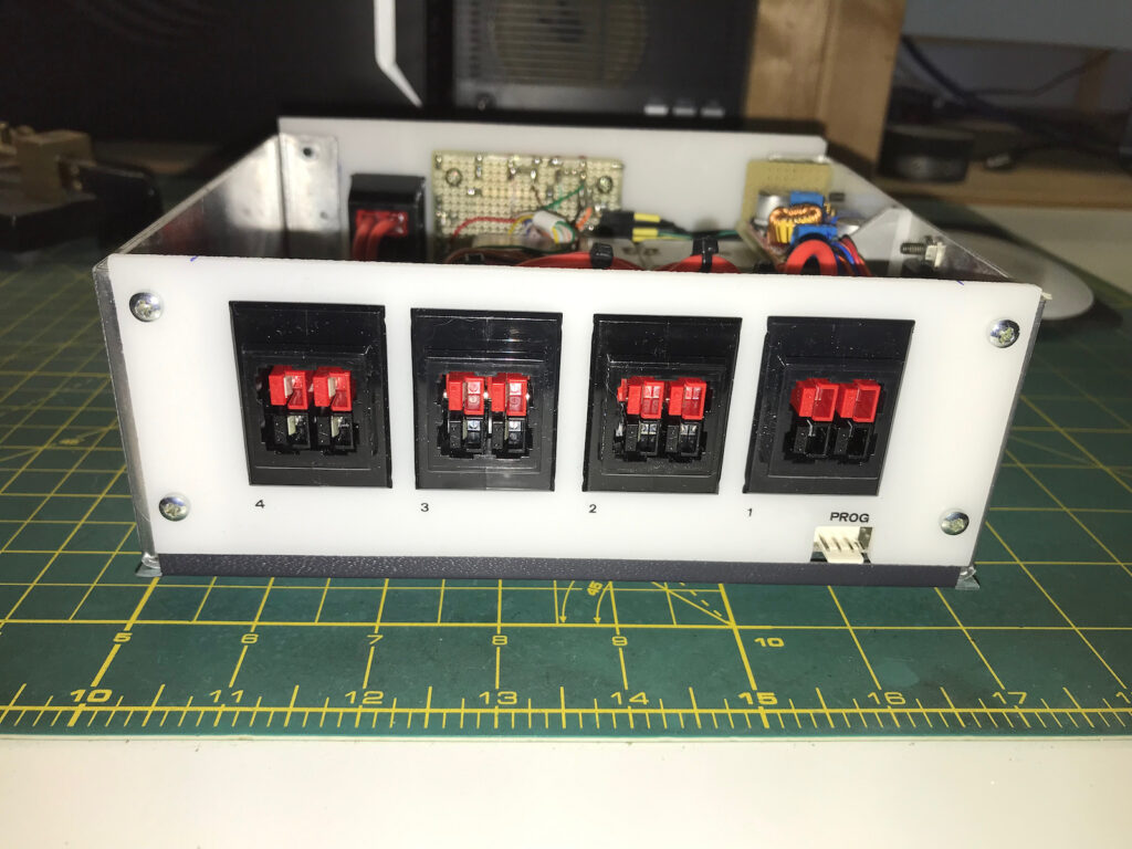
La mia realizzazione / My built


Il mio utilizzo / How I use it
Nella mia stazione lo utilizzo in questo modo / Here is how I use it in my shack
….. that’s all folks ! Have fun
TU 73 de Giorgio IK1BXN
mail to : ik1bxn@ik1bxn.it